Prismatic cell with integrated cooling plate

Active Publication Date: 2012-09-13
GM GLOBAL TECH OPERATIONS LLC
View PDF8 Cites 9 Cited by
  • Summary
  • Abstract
  • Description
  • Claims
  • Application Information

AI Technical Summary

Benefits of technology

[0006]In concordance with the instant disclosure, a battery cell assembly having a simplified design and a reduced number of parts, and which has decoupled electrical and thermal

Problems solved by technology

When overheated or otherwise exposed to high-temperature environments,

Method used


Image

  • Prismatic cell with integrated cooling plate
  • Prismatic cell with integrated cooling plate
  • Prismatic cell with integrated cooling plate

Examples


Example

[0016]The following detailed description and appended drawings describe and illustrate various embodiments of the invention. The description and drawings serve to enable one skilled in the art to make and use the invention, and are not intended to limit the scope of the invention in any manner.

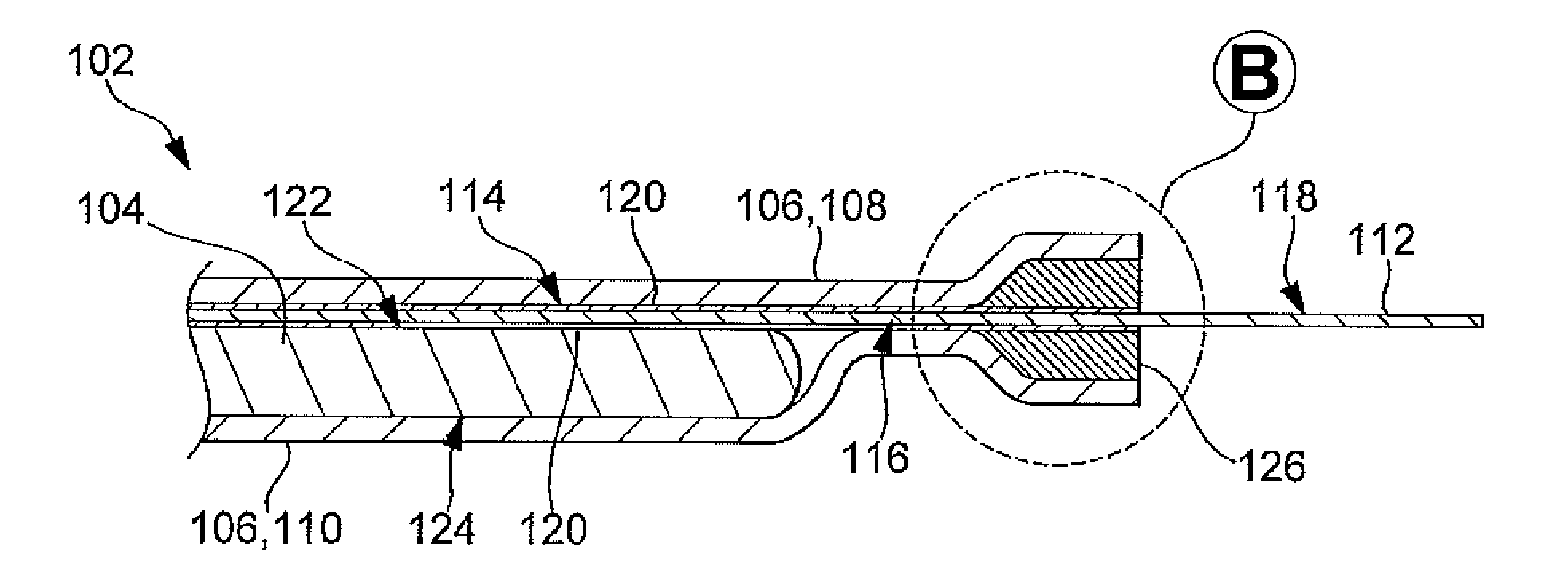
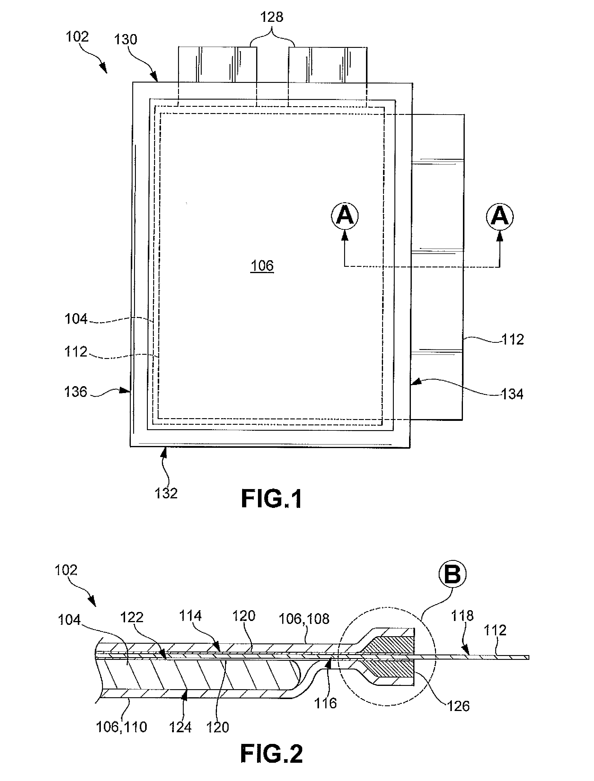
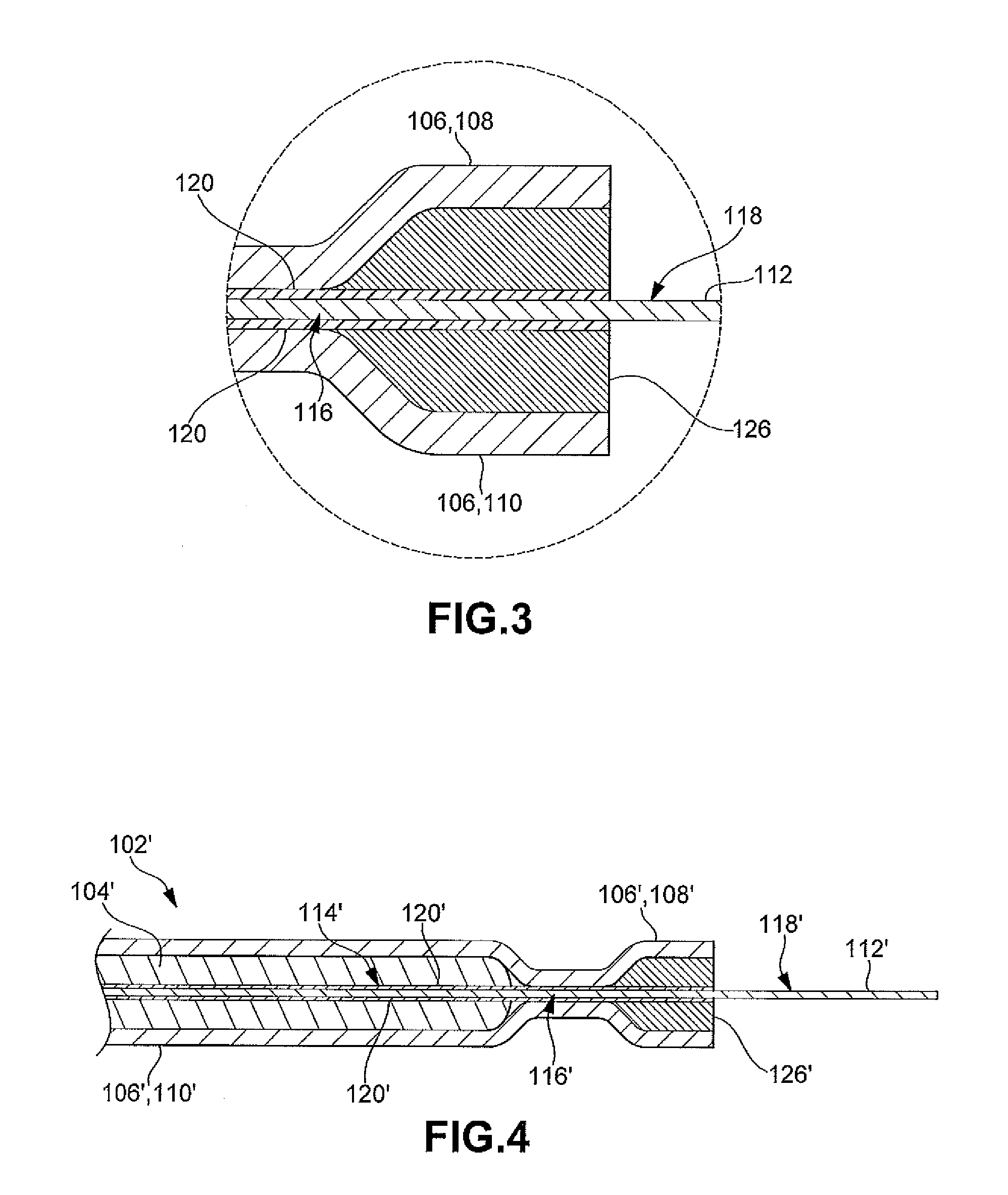
[0017]With reference to FIGS. 1-3, a battery cell assembly 102 according to one embodiment the present disclosure is shown. The battery cell assembly 102 includes a battery cell 104 having active material configured to generate power from an electrochemical reaction. The battery cell 104 shown is a prismatic battery cell. As a nonlimiting example, the battery cell 104 may be a prismatic lithium ion (Li-ion) pouch cell. It should be appreciated that other types of the battery cells 104, employing a different structure and electrochemistry, may also be used within the scope of the present invention.

[0018]The battery cell assembly 102 has a pouch 106 formed from an insulating material. The pouch ...


PUM


Abstract

A battery cell assembly includes a battery cell including active material configured to generate power from an electrochemical reaction. A pouch formed from insulating material envelopes the battery cell. The battery cell assembly further includes a cooling element having an internal portion and an external portion. The internal portion is disposed within the pouch and is in thermal communication with the battery cell. The external portion is disposed outside of the pouch. The cooling element is configured to transfer heat generated during the electrochemical reaction away from the battery cell.

Description

FIELD OF THE INVENTION[0001]The present disclosure relates to a battery cell assembly and more particularly to a battery cell assembly with an integrated cooling element.BACKGROUND OF THE INVENTION[0002]A battery cell has been proposed as a clean, efficient and environmentally responsible power source for electric vehicles and various other applications. One type of battery cell is known as the lithium-ion battery. The lithium-ion battery is rechargeable and can be formed into a wide variety of shapes and sizes so as to efficiently fill available space in electric vehicles. For example, the battery cell may be prismatic in shape to facilitate a stacking of the battery cells. A plurality of individual battery cells can be provided in a battery pack to provide an amount of power sufficient to operate electric vehicles.[0003]Typical prismatic battery cells have a pair of plastic coated metal layers fused around a periphery of the battery cell in order to seal the battery cell component...

Claims


Application Information

Patent Timeline
IPC IPC(8): H01M10/50
CPCH01M10/052H01M10/5004H01M10/5032H01M10/5042Y02T10/7011H01M10/5053H01M2220/20Y02E60/12H01M10/0585H01M10/5046H01M10/613H01M10/647H01M10/654H01M10/6551H01M10/6554Y02E60/10Y02P70/50
Inventor KUMAR, VINODDEMING, JR., RICHARD C.
Owner GM GLOBAL TECH OPERATIONS LLC
Why Eureka
Try Eureka