Drum commutator and method for producing the same

Inactive Publication Date: 2005-01-18
KOLEKTOR D O O
View PDF17 Cites 5 Cited by
  • Summary
  • Abstract
  • Description
  • Claims
  • Application Information

AI Technical Summary

Benefits of technology

From the foregoing explanations of the present invention, it is evident that it provides a drum commutator having characteristics that have been unknown heretofore. In particular, despite low manufacturing costs, the inventive drum commutator is characterized by outstanding quality, due in

Problems solved by technology

The expense associated with this step is small; and t

Method used


Image

  • Drum commutator and method for producing the same
  • Drum commutator and method for producing the same
  • Drum commutator and method for producing the same

Examples


Example

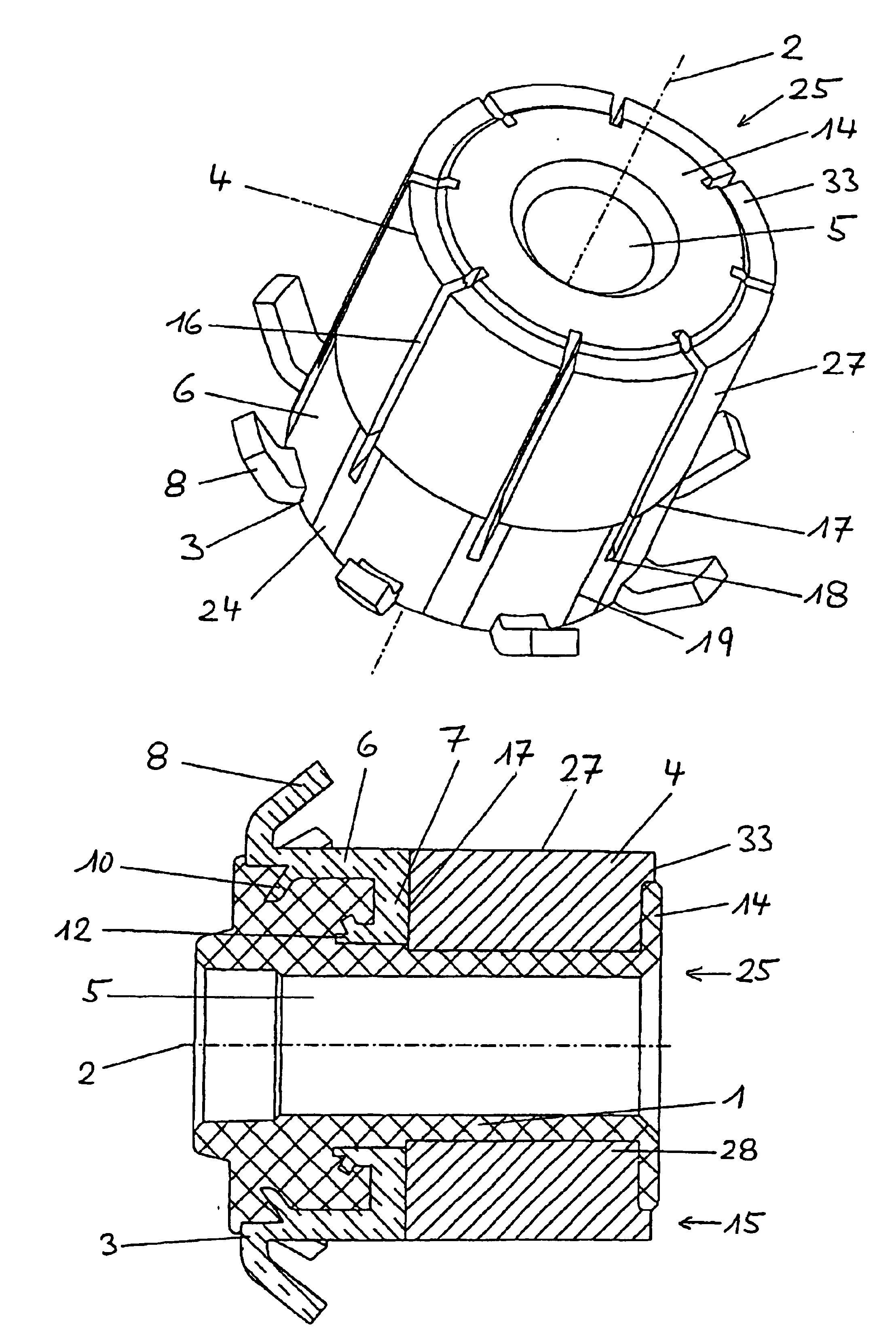
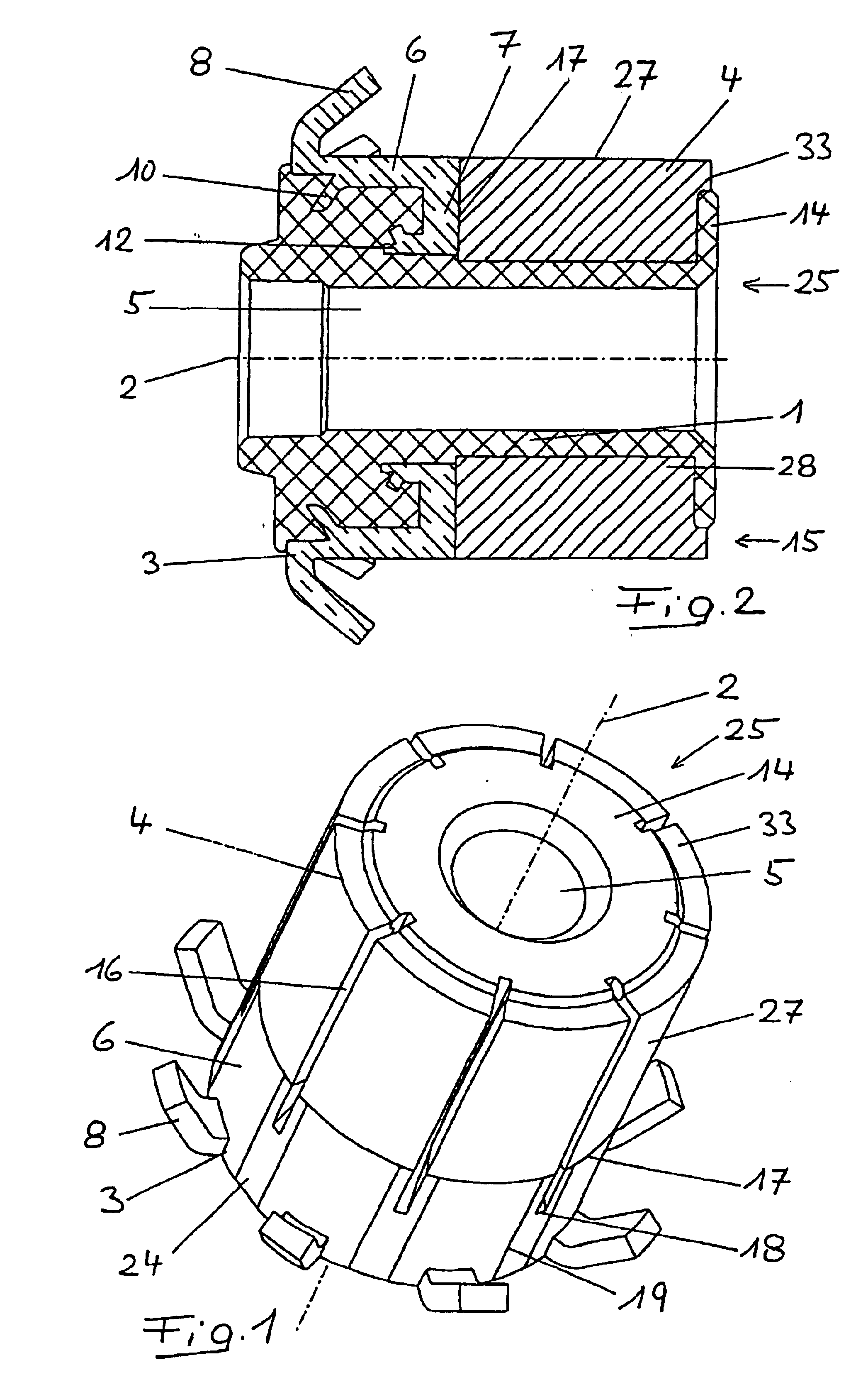
The drum commutator illustrated in FIGS. 1 and 2 comprises a support body 1 made from insulating compression-molding material, eight metal conductor segments 3 disposed in uniform distribution around the axis 2, and eight carbon segments 4, each of which is joined in electrically conductive relationship to one conductor segment 3. Support body 1 is provided with a central bore 5. In this scope, the drum commutator according to FIGS. 1 and 2 corresponds to the prior art according to DE 3150505 A1, and so the basic construction need not be explained in more detail.

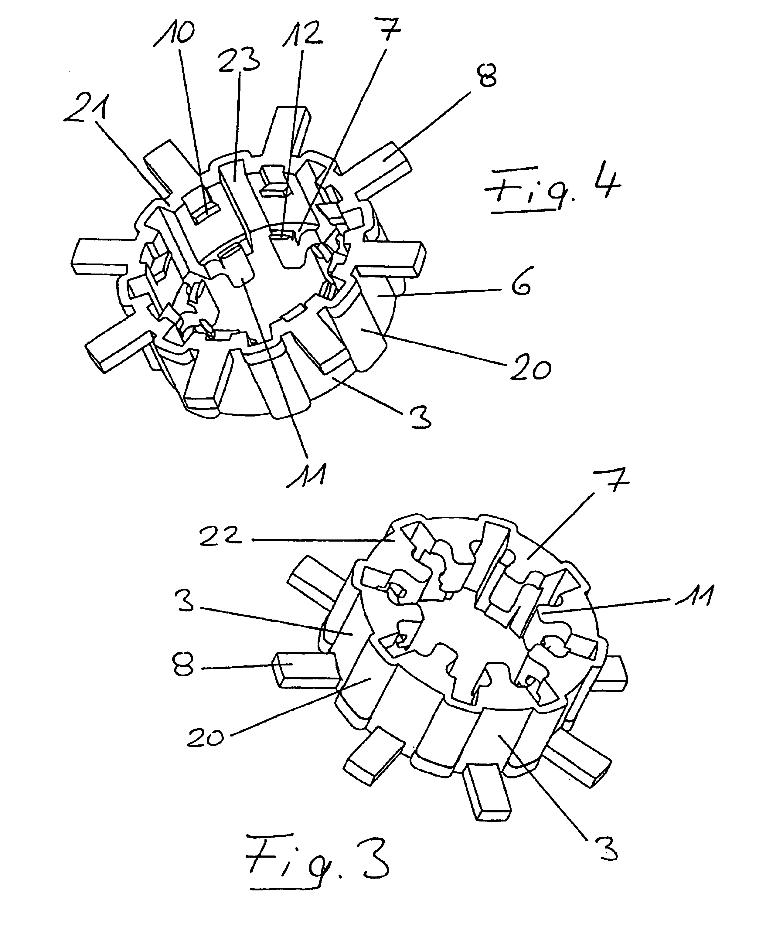
As will be explained in detail hereinafter, conductor segments 3 made of copper are obtained from the conductor blank illustrated in FIGS. 3 and 4. They comprise two main regions, namely terminal region 6 and contact region 7. On each of the terminal regions 6 there is disposed a terminal lug 8. This functions as the electrically conductive connection of a winding wire to conductor segment 3 in question. Terminal lugs may be...


PUM

PropertyMeasurementUnit
Thicknessaaaaaaaaaa
Electrical conductivityaaaaaaaaaa
Lengthaaaaaaaaaa

Abstract

The invention relates to a drum commutator comprising a cylinder-shaped support base (1) produced from an insulating pressed material, a plurality of metal conductor segments (3) with terminal lugs (8) disposed thereon and an equal amount of carbon segments (4) that are electrically connected to the conductor segments (3). The drum commutator, adjacent to the terminal lugs (8), further comprises an annular, closed substantially regularly cylindrical surface (19) with alternating pressed material zones and metal zones, as well as a metallized inner surface of the carbon segments (4) that communicates with the support base (1). When producing such a drum commutator, the conductor segments (3) are preferably first connected to a conductor blank via bridge portions which are removed once the conductor blank has been assembled with a carbon cylinder and the support base has been injection-molded onto it.

Description

FIELD OF THE INVENTIONThe present invention relates to a drum commutator comprising a barrel-shaped support body made of insulating compression-molding material, a plurality of conductor segments and an equal number of carbon segments, which are joined to the conductor segments in electrically conductive relationship. The present invention also relates to a method for producing such a drum commutator.BACKGROUND OF THE INVENTIONFor certain applications in electrical machinery, especially those that depend on the current intensity to be transmitted in connection with the installation conditions, there are used drum commutators, also known as cylindrical commutators, in which the brush contact face is disposed on a regular cylinder concentric with the commutator axis. In addition to drum commutators with metal brush contact face there are known several modifications of drum commutators of the type cited in the introduction, in which the brush contact face is disposed on the carbon segm...

Claims


Application Information

Patent Timeline
IPC IPC(8): H01R39/00H01R39/04H01R13/00H01R4/00H01R39/32H01R43/08H02K13/00H02K15/02
CPCH01R39/045Y10T29/49011H02K13/00
Inventor POTOCNIK, JOZE
Owner KOLEKTOR D O O
Why Eureka
Try Eureka