Device for Changing Pitch Between Light Beam Axes, and Substrate Exposure Apparatus

Active Publication Date: 2007-12-06
ADTEC ENG
View PDF4 Cites 7 Cited by
  • Summary
  • Abstract
  • Description
  • Claims
  • Application Information

AI Technical Summary

Benefits of technology

[0011]According to the present invention, since multiple pairs of light beams can be arranged in the board thickness direction even when there are provided one first transparent member and one second t

Problems solved by technology

However, the beam-pitch-reducing means without beam diameter change described in Japanese Patent Application Laid-Open Publication No. 2005-316349, not only a large number of parts are requi

Method used


Image

  • Device for Changing Pitch Between Light Beam Axes, and Substrate Exposure Apparatus
  • Device for Changing Pitch Between Light Beam Axes, and Substrate Exposure Apparatus
  • Device for Changing Pitch Between Light Beam Axes, and Substrate Exposure Apparatus

Examples


Embodiment Construction

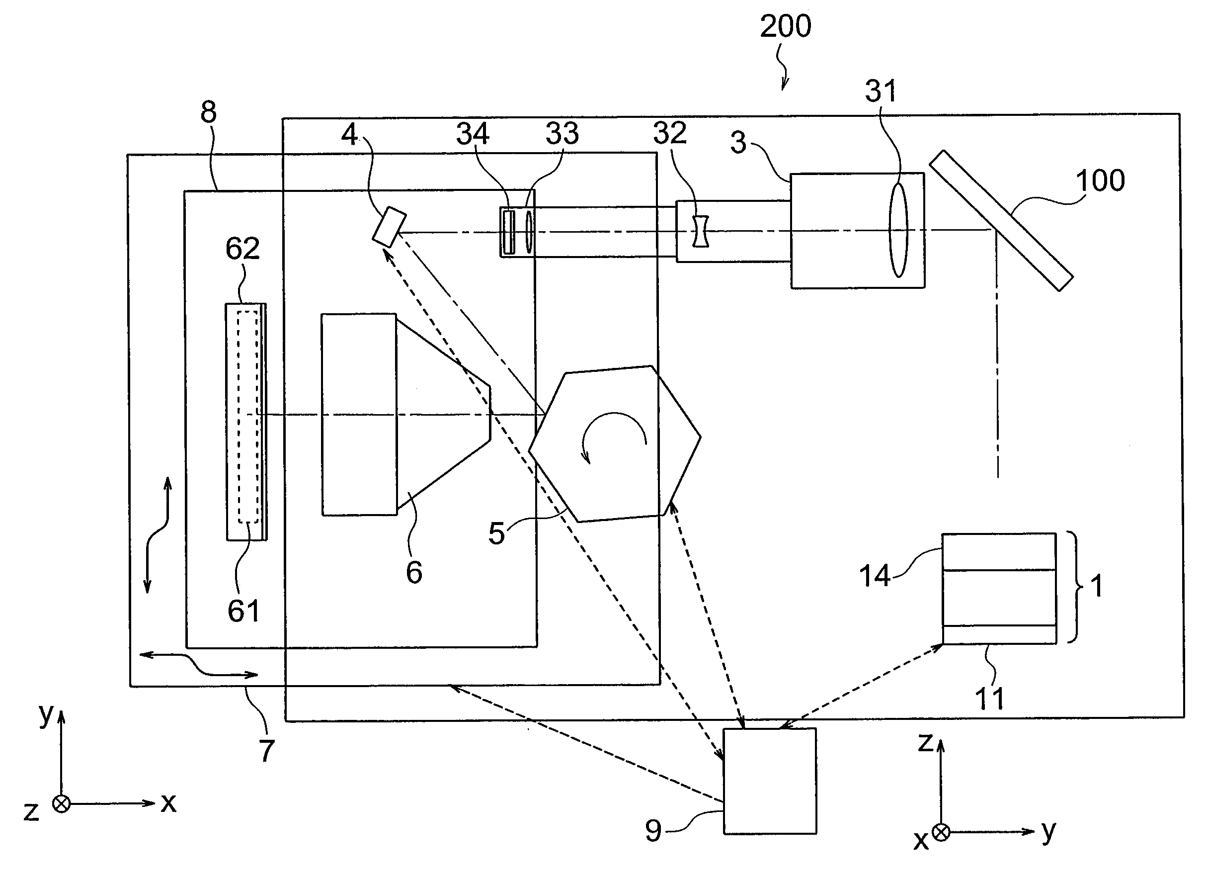
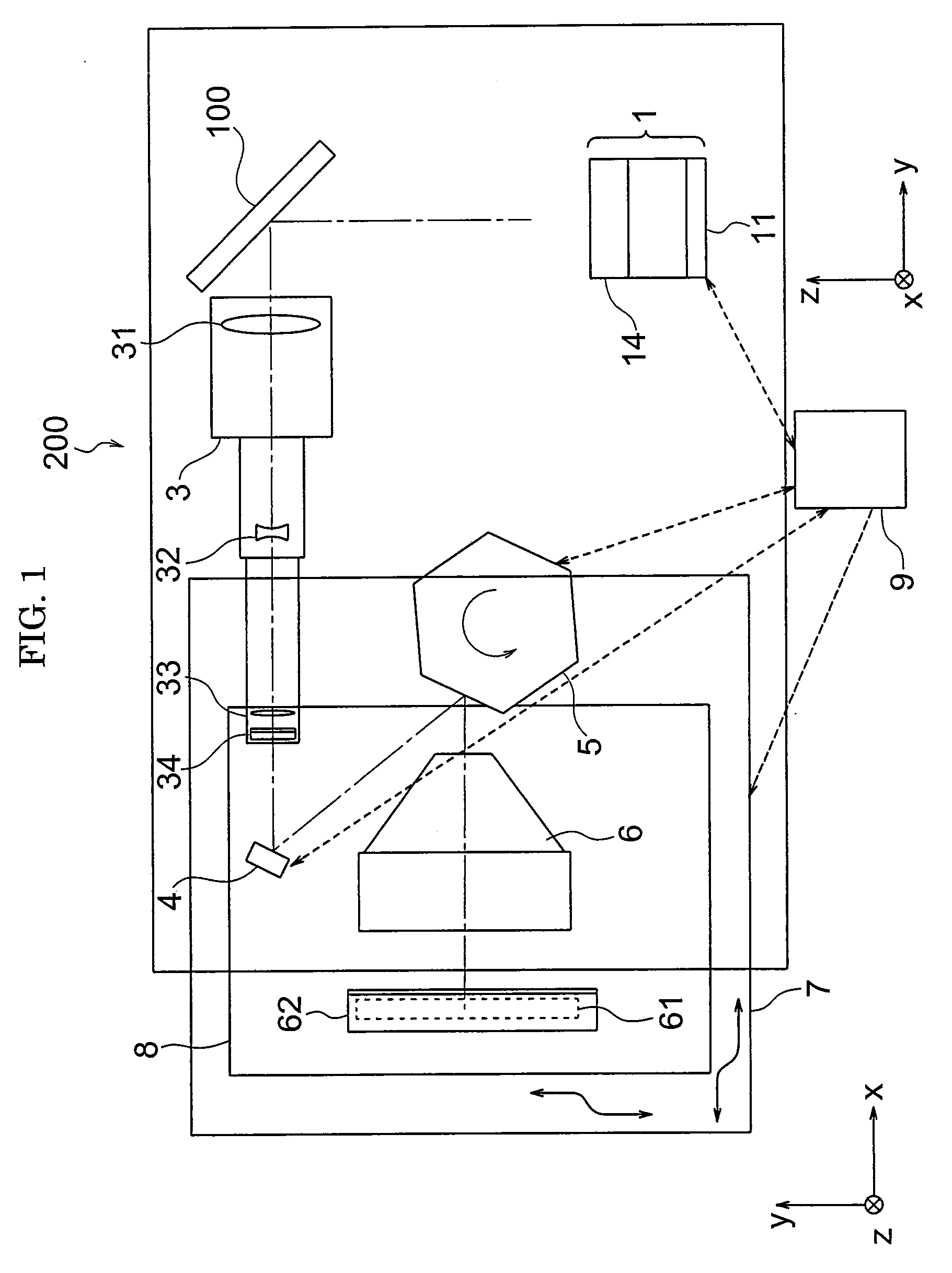
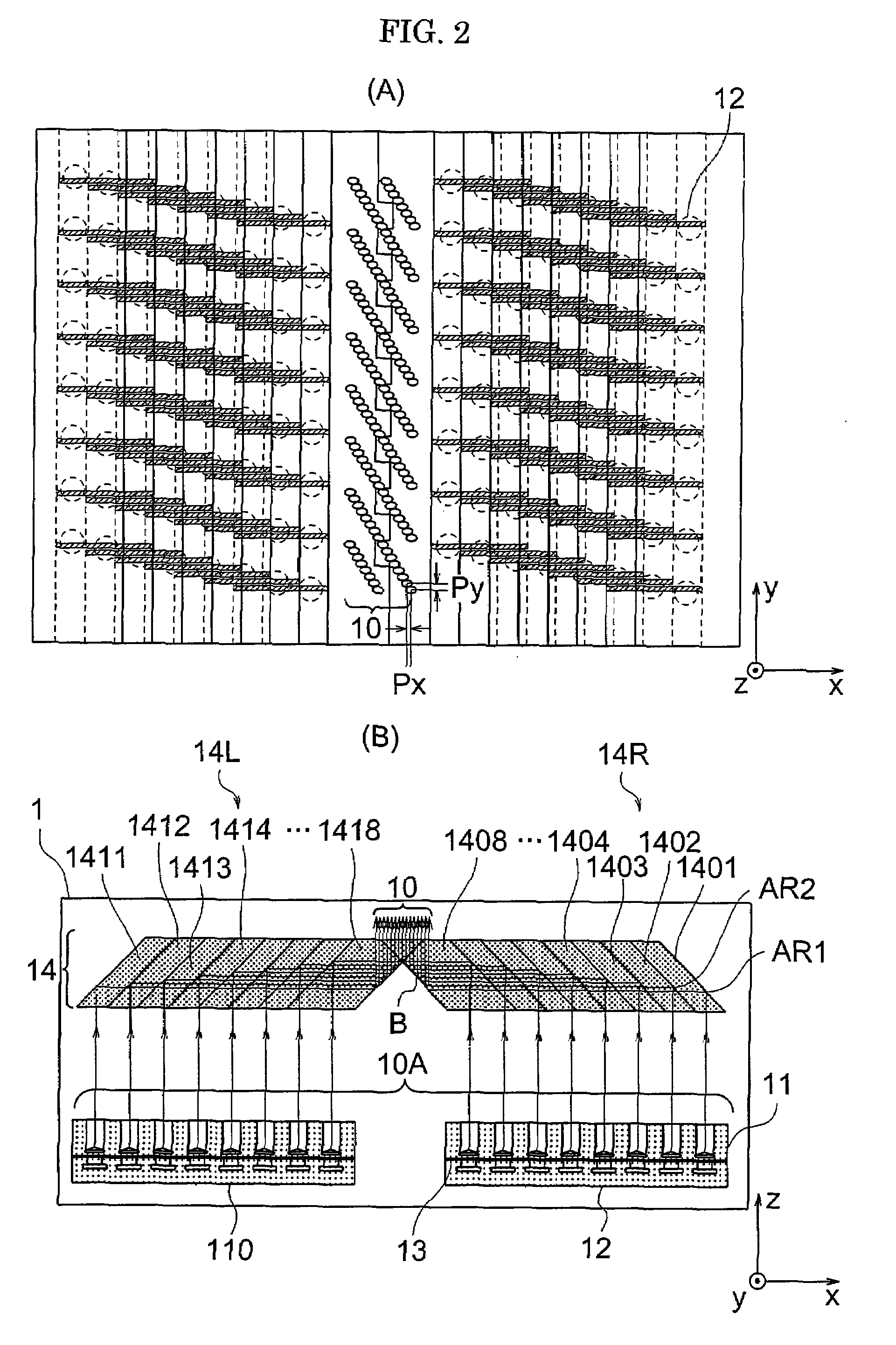
[0020]FIG. 1 is a view showing the general configuration of an exposure apparatus according to an embodiment of the present invention, FIGS. 2A and 2B are views illustrating a light source optical system according to an embodiment of the present invention, FIGS. 3A and 3B are views illustrating the configuration of an integrated parallel-glass unit 14L according to an embodiment of the present invention, FIG. 4 is a view illustrating the operation of an integrated parallel-glass unit according to an embodiment of the present invention, FIG. 5 is a view showing another arrangement example of an integrated parallel-glass unit, FIG. 6 is a view showing the arrangement of light beams in an exposure surface, and FIG. 7 is a view showing the general configuration of another exposure apparatus according to an embodiment of the present invention.

[0021]An exposure apparatus 200 includes a light source optical system 1, a mirror 100, a long-focus lens 3, a mirror 4, a polygon mirror 5, an fθ ...


PUM


Abstract

A parallel glass which is a prism having a parallelogram-shaped cross section in an x-y direction, and parallel glasses which are prisms having a parallelogram-shaped cross section in the x-y direction and each include grooves formed in one surface in a z direction perpendicular to the x-y direction, are stacked in direct contact with each other such that the grooves are located on the inside, and light trying to enter the grooves is subjected is total reflection, thereby changing incident parallel beams with a pitch of 13 mm into emergent parallel beams with a pitch of 1 mm.

Description

BACKGROUND OF THE INVENTION[0001](1) Field of the Invention[0002]The present invention relates to a device for changing a pitch between light beam axes to another desired pitch, and a maskless substrate exposure apparatus which includes the device for changing the pitch between the axes of the light beams outputted from multiple light sources arranged in a matrix serve as its light source.[0003](2) Description of the Related Art[0004]In the related art, to form a pattern on a printed circuit board, a TFT substrate or color filter substrate of a liquid crystal display, or a substrate of a plasma display by exposure, a mask that serves as a master for the pattern is produced, and this master mask pattern is transferred onto the above-mentioned substrate by exposure with a mask exposure apparatus.[0005]However, substrates are becoming increasingly larger in size in recent years. Moreover, the time taken to design and manufacture these substrates is becoming increasingly shorter. In vie...

Claims


Application Information

Patent Timeline
IPC IPC(8): G03B27/42
CPCG02B5/045G02B17/04G02B26/12G03F7/704G03F7/7005G03F7/70791G03F7/70391G03F7/2057G03F7/20G02B26/10
Inventor OSHIDA, YOSHITADANAITO, YOSHITATSUSUZUKI, MITUHIROYAMAGUCHI, TSUYOSHIMARUYAMA, SHIGENOBU
Owner ADTEC ENG
Why Eureka
Try Eureka