Ink jet head and ink jet recording apparatus

Active Publication Date: 2007-01-25
SII PRINTEK
View PDF3 Cites 9 Cited by
  • Summary
  • Abstract
  • Description
  • Claims
  • Application Information

AI Technical Summary

Benefits of technology

[0015] As described above, according to the invention, when ink is introduced via one ink flow path, this ink can be guided to all the head chips that constitute a head chip

Problems solved by technology

Therefore, the size of the ink jet head in the direction of thickness is increased, and the weight ca

Method used


Image

  • Ink jet head and ink jet recording apparatus
  • Ink jet head and ink jet recording apparatus
  • Ink jet head and ink jet recording apparatus

Examples


Embodiment Construction

[0031] The present invention will now be described in detail by referring to the preferred embodiments.

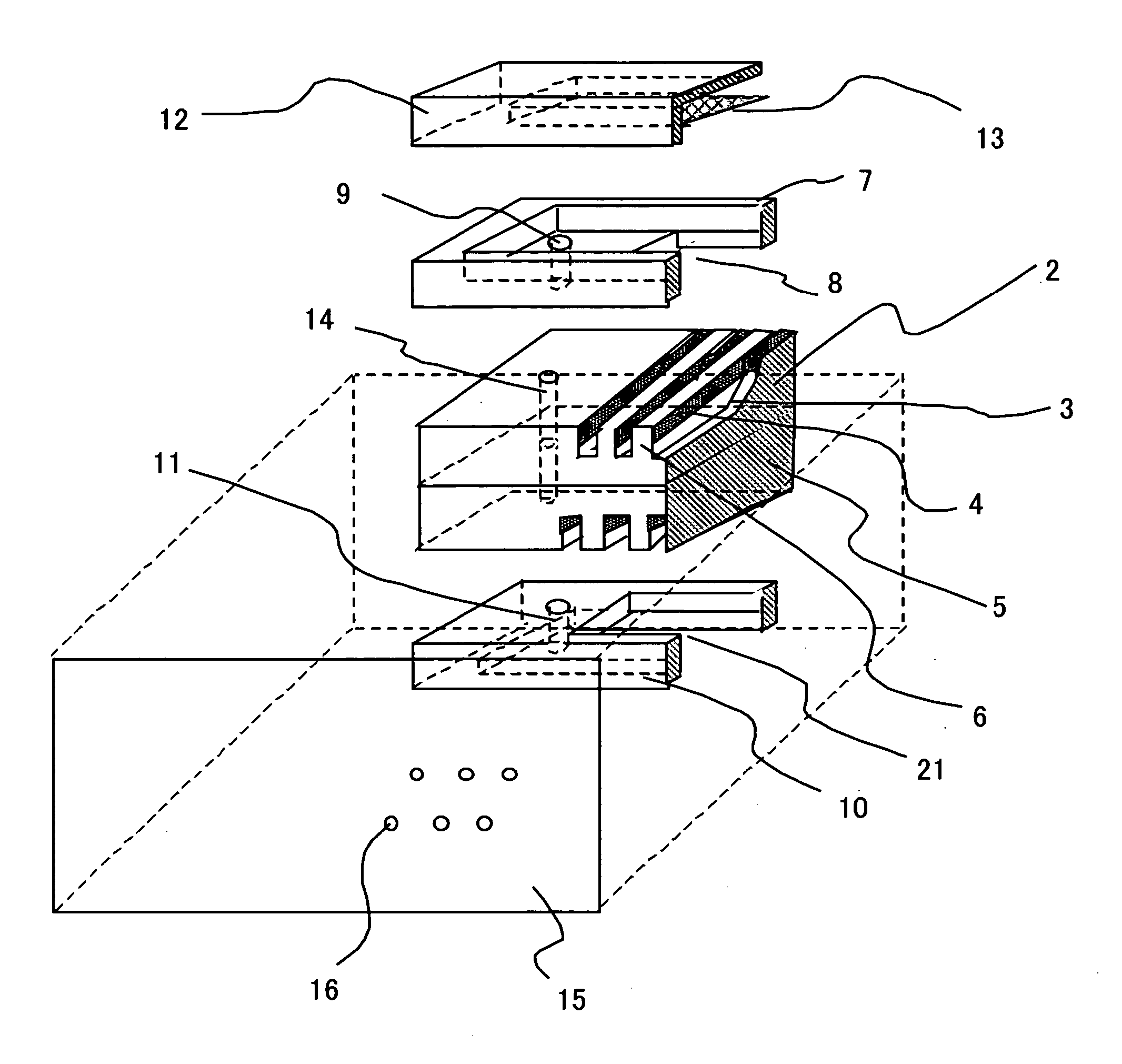
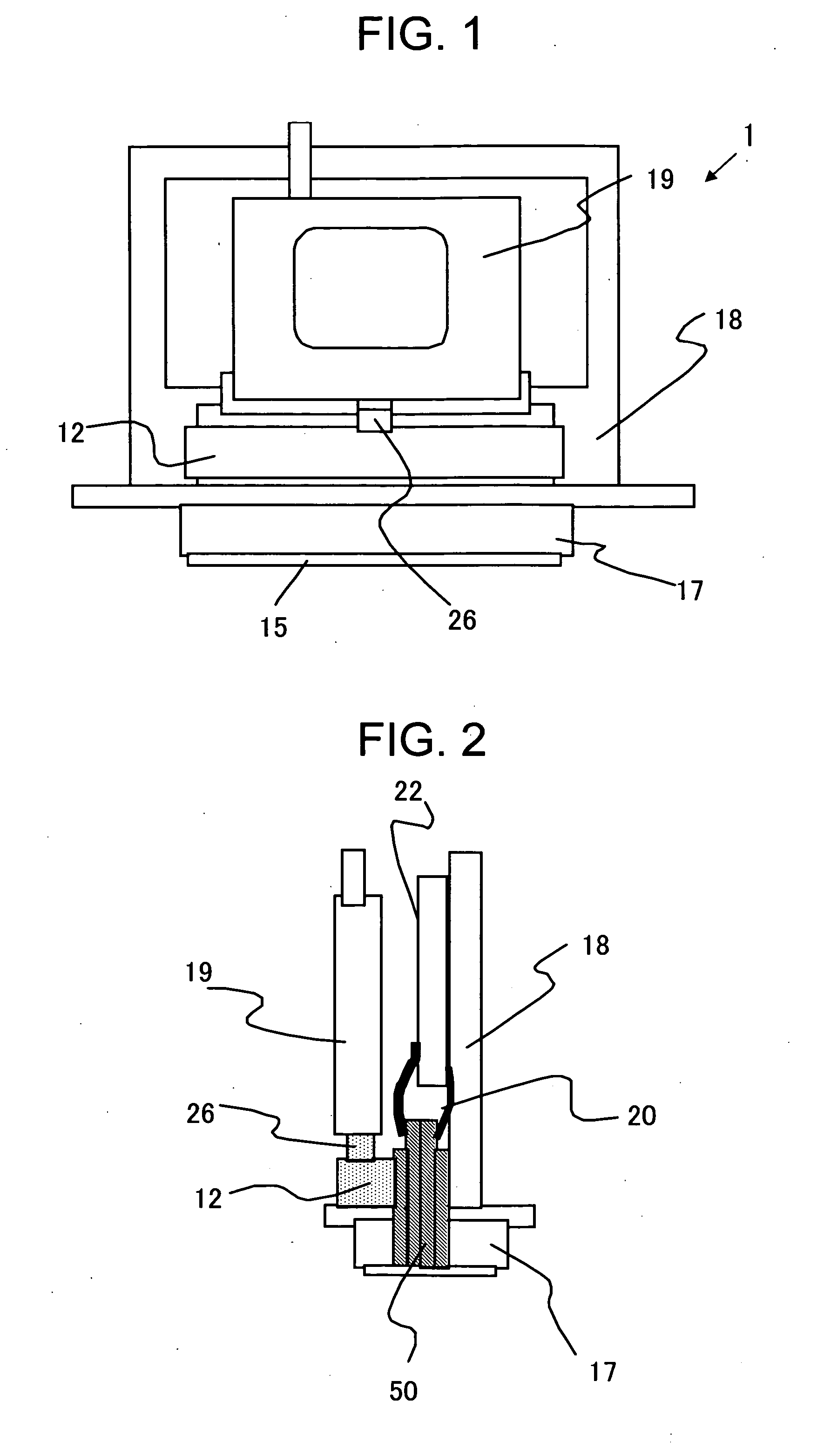
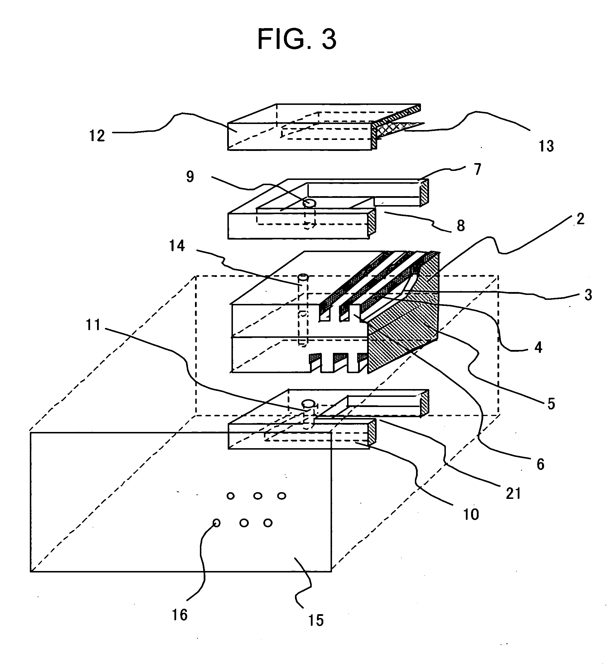
[0032]FIG. 1 is a front view of the entire ink jet head according to a first embodiment of the present invention, and FIG. 2 is a schematic cross-sectional view of the entire ink jet head according to the first embodiment. FIG. 3 is an exploded diagram showing the periphery of the discharge pressure generator of the ink jet head for the first embodiment. FIG. 4A is a plan view of the head chip block of the ink jet head of the first embodiment, and FIG. 4B is a cross-sectional view of this head chip block, taken along the line indicated by arrows A-A′. FIG. 5 is a schematic front view of the essential portion of the ink jet head for the first embodiment, and FIGS. 6 and 7 are a cross-sectional view taken along the line indicated by arrows C-C′, and a cross-sectional view taken along the line indicated by arrows D-D′.

[0033] As shown in these drawings, an ink jet head 1 for the firs...


PUM


Abstract

A small, light ink jet head that is constituted by employing a laminated head chip is provided at a low price. According to the present invention, through holes are formed in a plurality of head chips, for a head chip block, for which independent ink flow paths are not provided, or for which guide holes are formed in the side faces of the head chips. With this arrangement, ink that is guided from an ink flow path can be supplied to all the head chips that constitute the head chip block.

Description

BACKGROUND OF THE INVENTION [0001] 1. Field of the Invention [0002] The present invention relates to an ink jet head employed for an ink jet recording apparatus that discharges ink droplets to record images on a recording medium. [0003] 2. Related Background Art [0004] Conventionally, an ink jet recording apparatus is known that records characters and images on a recording medium by employing an ink jet head that includes a plurality of nozzles from which ink is discharged. The type of ink jet head frequently employed includes, as a single unit, multiple nozzles, pressure generators and ink guide holes, and an ink jet head wherein multiple arrays of nozzles and pressure generator arrays are provided is well known. FIG. 12 is a schematic cross-sectional view of an example ink jet head unit wherein two nozzle arrays are arranged with their positions shifted relative to each other. FIG. 13 is a plan view of a head chip block, and FIG. 14 is a schematic cross-sectional view of the entir...

Claims


Application Information

Patent Timeline
IPC IPC(8): B41J2/04
CPCB41J2/14209B41J2002/14419B41J2002/14403B41J2/145
Inventor KOSEKI, OSAMU
Owner SII PRINTEK
Why Eureka
Try Eureka