
Apparatus and Method for Improved Optical Detection of Particles in Fluid

Active Publication Date: 2009-06-18
RGT UNIV OF CALIFORNIA
View PDF8 Cites 25 Cited by
  • Summary
  • Abstract
  • Description
  • Claims
  • Application Information

AI Technical Summary

Benefits of technology

[0010]The present inventors have recognized the desirability of achieving improved photonic designs and technologies for detecting small objects or particles, for use in various applications such as flow cytometry involving the use of microfluidic components. For example, the present inventors have recognized the desirability of providing a cost effective solution to the problem of fluorescence (and side scattering) detection in flow cytometry and, more particularly, have recognized the importance of at least one of (a) integrating optical components with fluidic circuits to reduce the size and weight of the overall system, and (b) developing innovative architectures of photonic circuits to achieve desired levels of sensitivity without the need for expensive components such as lasers (e.g., main frame lasers) and / or ultra sensitive detectors (e.g., photomultiplier tubes (PMTs)).
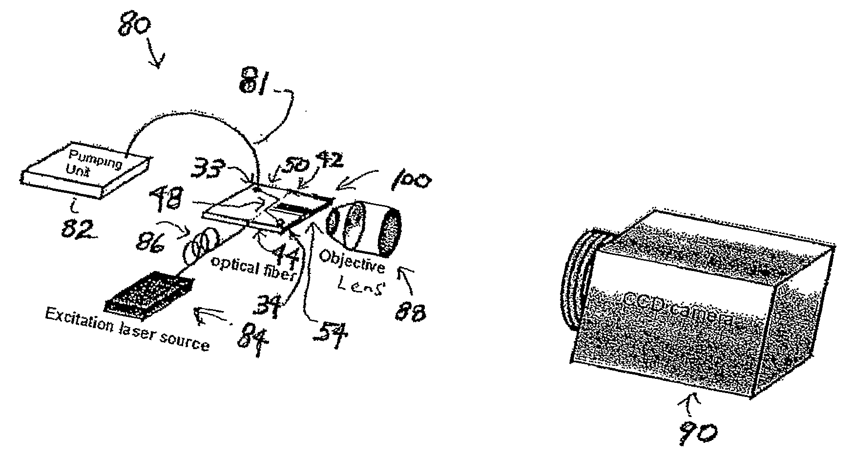
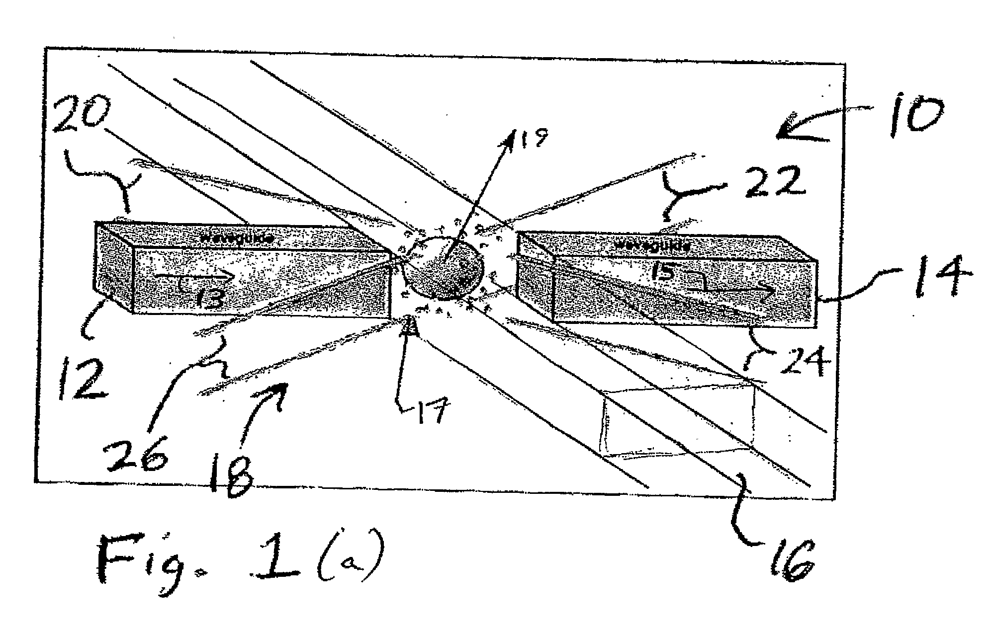
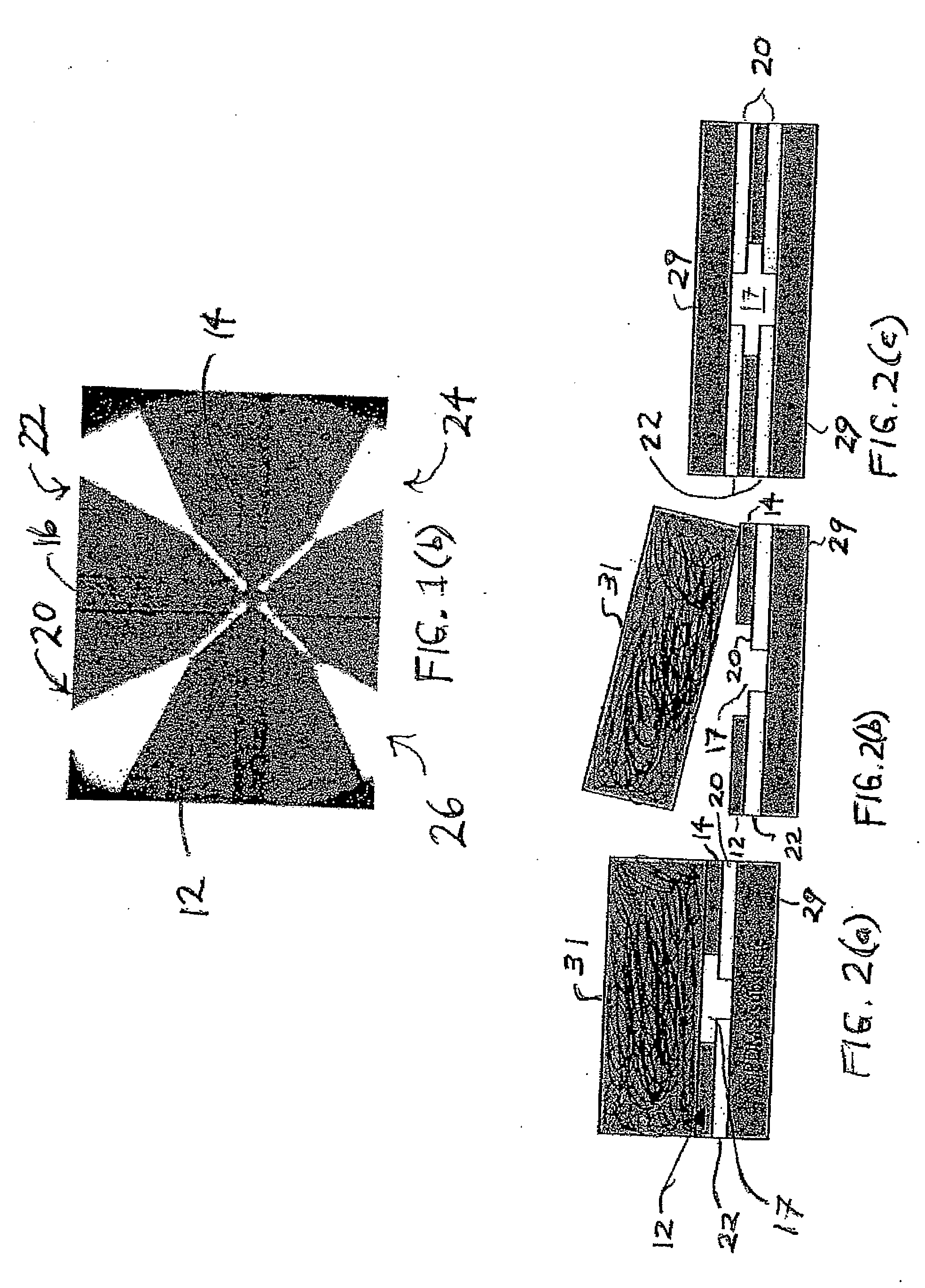
[0011]In accordance with at least some embodiments of the present invention, to achieve such goals the present inventors propose a microfluidic-photonic integrated circuit optical interrogation device that can be utilized as a microfabricated flow cytometer. The device includes a photonic circuit integrated monolithically with the microfluidic channels such that the optical interrogation zones are in the proximity of and well aligned to the optical waveguides that collect the fluorescence and / or scattering light signals. The use of such a waveguide approach to replace free-space optics eliminates the needs for lenses and precision mechanics for optical alignment, making significant size and weight reduction possible. The device can be fabricated using a fluidic-photonic integrated circuit FPIC) process.

Problems solved by technology

However, even though the size of a flow cytometer has been reduced from a piece of equipment occupying an entire room to a table top system with ever increasing functionality and performance, flow cytometers continue to cost between $150K and $1 M, and consequently remain a tool affordable only by major medical centers and laboratories.
Although rapid progress has been made in microfluidics that is applicable to flow cytometry, the scheme of optical detection employed in flow cytometry has not experienced similarly important advances or changes.
As a result, the expensive and bulky optical setup currently necessary for fluorescence detection threatens to become a bottleneck restricting the realization of compact, low-cost flow cytometers.
Additionally, the relatively high cost of lasers and light detectors for use in flow cytometry is further exacerbated when one reduces the size of the overall system.

Method used


Image

  • Apparatus and Method for Improved Optical Detection of Particles in Fluid
  • Apparatus and Method for Improved Optical Detection of Particles in Fluid
  • Apparatus and Method for Improved Optical Detection of Particles in Fluid

Examples


Embodiment Construction

[0029]As described in detail below, the present invention is intended to encompass a variety of different embodiments of microfluidic-photonic integrated circuits and similar devices, as well as systems that implement those integrated circuits and devices. Such devices can be employed for a variety of purposes including, for example, to detect the presence of biological particles such as cells and DNA or other particles, and / or in various applications such as flow cytometry and other techniques. Additionally, the present invention is intended to encompass various methods of operating and manufacturing such integrated circuits and other devices (and / or systems that implement those integrated circuits and devices). In at least some embodiments, for example, microfluidic-photonic-dielectrophoretic integrated circuits can be fabricated by way of a process involving micro-molding, polymer bonding, and channel waveguides with capillary filling. At least some of the circuits described here...


PUM

PropertyMeasurementUnit
Timeaaaaaaaaaa
Flow rateaaaaaaaaaa
Sensitivityaaaaaaaaaa

Abstract

A number of fluidic-photonic devices for allowing optical detection, systems employing such devices, and related methods of operation and fabrication of such devices are disclosed herein. In at least some embodiments, the devices can serve as flow cytometry devices and / or employ microfiuidic channels. Also, in at least some embodiments, the devices are fluidic-photonic integrated circuit (FPIC) devices that employ both fluidic channels and one or more waveguides capable of receiving and / or delivering light, and that can be fabricated using polymeric materials. The fluidic-photonic devices in at least some embodiments are capable of functionality such as on-chip excitation, time-of-flight measurement, and can experience enhanced fluorescence detection sensitivity. In at least some embodiments, the devices employ detection waveguides that are joined by way of a waveguide demultiplexer. In additional embodiments, a variety of techniques can be used to process information received via the waveguides, including an iterative cross-correlation process.

Description

CROSS-REFERENCE TO RELATED APPLICATIONS[0001]This application claims the benefit of U.S. provisional patent application No. 60 / 731,551 entitled “Optical Detection of Suspended Micro-Objects Using Array Waveguides” filed on Oct. 28, 2005, which is hereby incorporated by reference herein.STATEMENT REGARDING FEDERALLY SPONSORED RESEARCH OR DEVELOPMENT[0002]This invention was made with United States Government support awarded by the following agencies: Air Force Office of Scientific Research (AFOSR) Grant No. F49620-02-1-0288. The United States Government has certain rights in this invention.FIELD OF THE INVENTION[0003]The present invention relates to systems and methods for optical detection and, more particularly, to systems and methods for detecting small objects or particles such as cells or DNA.BACKGROUND OF THE INVENTION[0004]Over a period of nearly five decades, flow cytometry has evolved from a simple technique for counting suspended particles (e.g., analytes, cells or DNA) in f...

Claims


Application Information

Patent Timeline
IPC IPC(8): C12Q1/02C12M1/34B29C69/00H05K3/00G01N21/53G01J1/58
CPCB01L3/502707Y10T29/49124B01L2200/0668B01L2300/0654B01L2300/0816B01L2400/0424B01L2400/0487G01N15/1434G01N15/1484G01N21/05G01N21/53G01N21/6408G01N2021/0346G01N15/1429G01N21/49B01L3/502715
Inventor LO, YU-HWALIEN, VICTOR JIECHEN, CHUN HAO RANDY
Owner RGT UNIV OF CALIFORNIA
Learn More