
Turbine generator

Inactive Publication Date: 2014-09-25
UNIV OF SOUTHAMPTON
View PDF15 Cites 26 Cited by
  • Summary
  • Abstract
  • Description
  • Claims
  • Application Information

AI Technical Summary

Benefits of technology

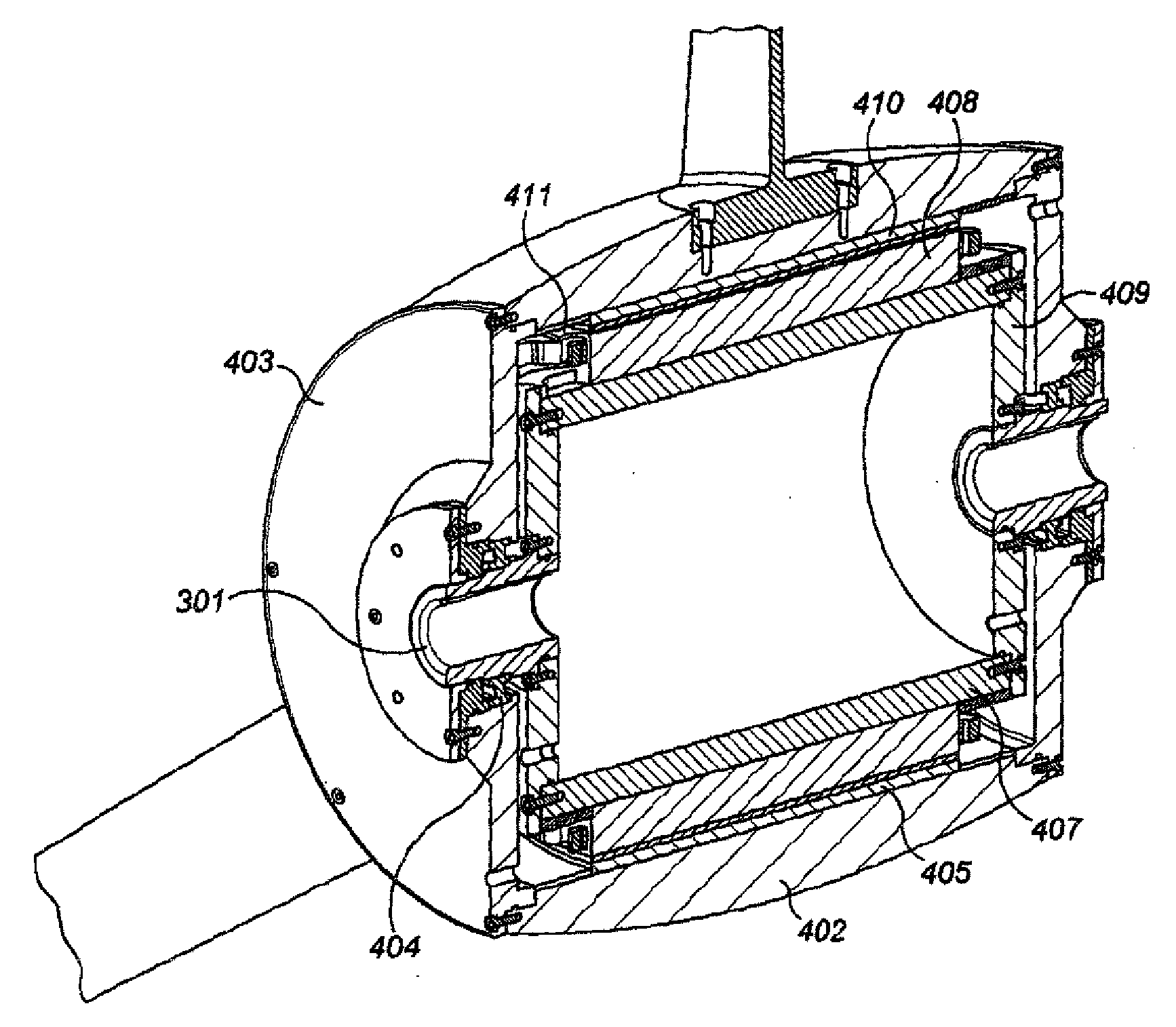
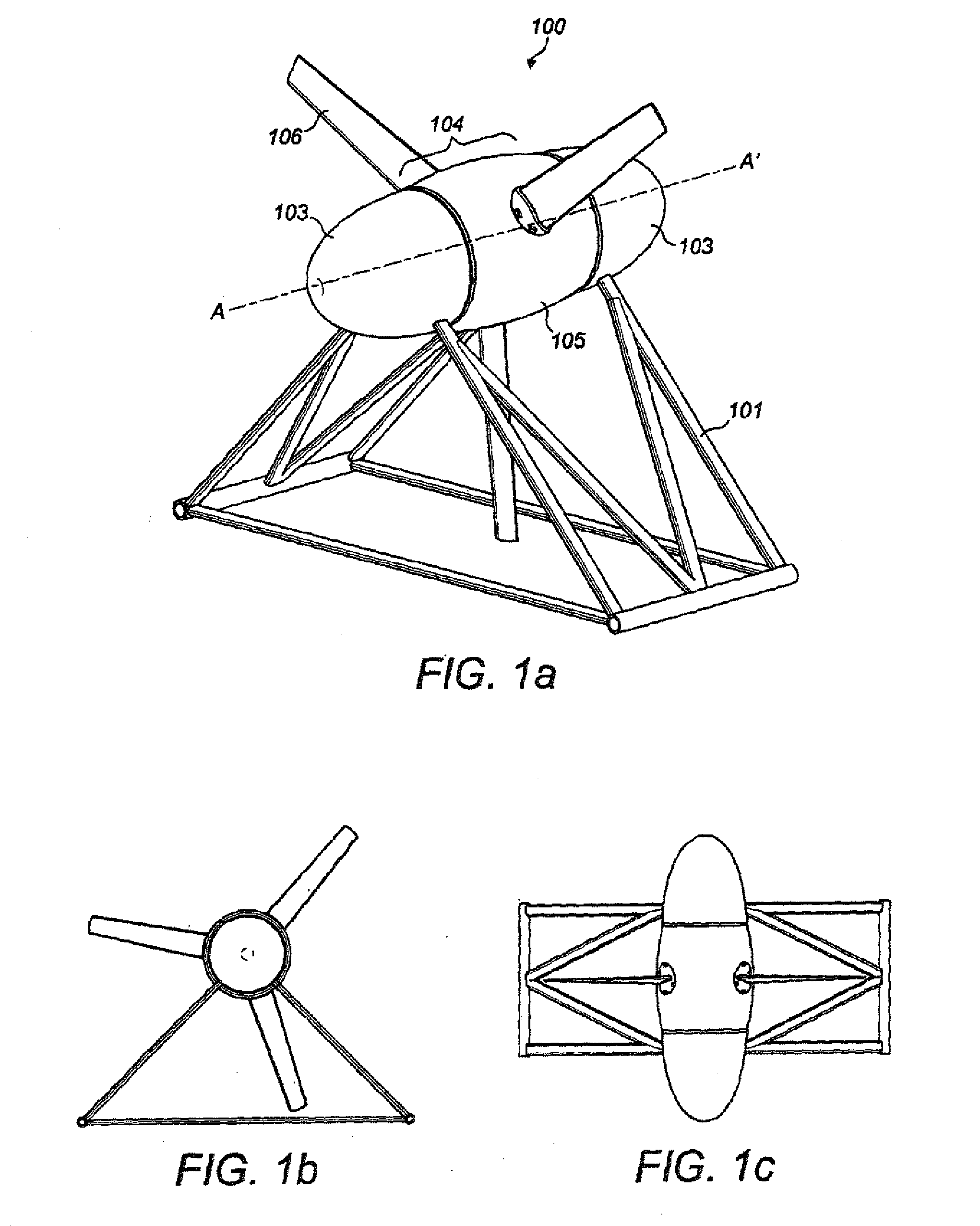
This patent describes a new turbine generator design that does not require a gearbox, making it mechanically simple. The generator uses permanent magnets to improve efficiency, and can be used in both liquid and air flow. The blades have a symmetrical cross-sectional profile that allows for bi-directional operation. The stator is supported by a frame or a support arm, and the core has slots and raised tooth coils connected in three groups for a three-phase output. The coils are connected to power electronic converters for increased fault tolerance. A generator control means monitors the output and controls the reacted torque to maximize power output. The rotor has internal surface mounted magnets, and a magnetic gear assembly can be added for increased speed. The technical effects of this design include improved efficiency, reliability, and reduced size and weight of the support structure.

Problems solved by technology

Climate change, pollution and energy security are the major problems of our time and addressing them requires a significant change in energy infrastructure.
However, marine current generators have to cope with harsh underwater conditions which can make them expensive to deploy and operate.
However, the mechanical complexity of the gearbox reduces reliability and decreases efficiency.
However, as mentioned above a bulky gearbox reduces the overall efficiency, which is generally compensated for by having longer blades to capture more energy from the water.
However, this increased blade length, together with the added mass of the gearbox may offset the generator size and cost savings.
The longer blades will not just simply increase the mass of the blades, which would need to be thicker to withstand the higher forces, they will also increase the overall thrust loading of the turbine, thus requiring bulkier blade root support structures as well as a bulkier overall support structure to hold the turbine in place.
Both solutions introduce complexity to the system and therefore decreased reliability and efficiency.
However, the duct is a large and costly component which increases the thrust loading on the device and therefore increases the cost of the supporting structure.
The breakage of a blade in a turbine with a rim would be more serious than a turbine without a rim because the unbalance forces are more severe.

Method used


Image

  • Turbine generator
  • Turbine generator
  • Turbine generator

Examples


Embodiment Construction

[0046]The power available from water current is proportional to the cube of the current speed. For tidal currents close to the shoreline in estuaries, and in channels between mainland and islands, the speed varies approximately sinusoidally with time, with a period relating to the different tidal components. Sites of most interest for exploitation have a maximum current speed in excess of 1.5 m / s, for example the Bristol Channel in the UK has a current speed of 2.5 m / s. Rivers can flow at speeds of up to 3.5 m / s and this can be increased further by damming.

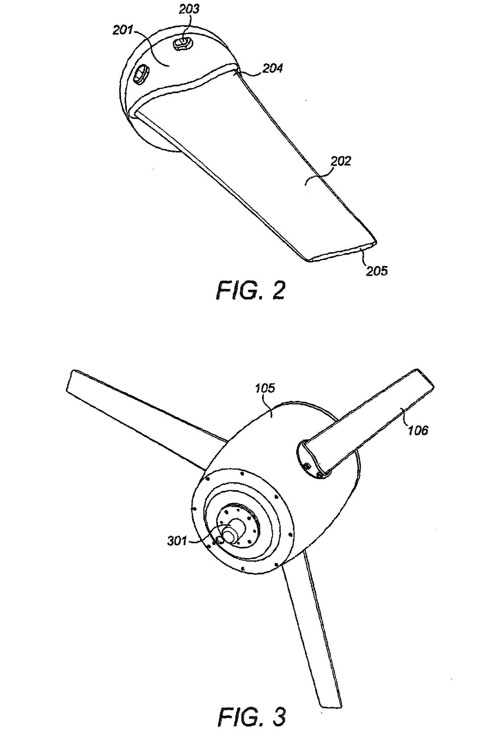
[0047]FIG. 1 is a view of a fluid turbine assembly 100 in accordance with an embodiment of the invention, suitable for extracting energy from flowing water, either tidal or river flows. The assembly comprises a cradle 101 supporting a hydro-dynamically efficient ellipsoidal structure. The ellipsoidal structure has a major axis A-A′ which, when the assembly is installed, is orientated such that it is generally aligned with the flui...


PUM


Abstract

The invention relates to the generation of electricity from flowing fluid and in the preferred embodiment to a horizontal axis turbine and generator assembly. The present invention is applicable to water turbines and the invention is described in relation to this application. It is however to be appreciated that it is applicable to wind turbines. The present invention provides turbine generator for generating electrical power from flowing fluid comprising a rotatable hub having an external surface and a rotational axis arranged, in use, parallel to the direction of the flow, a plurality of blades mounted on the external surface of the hub and extending radially outwards from the hub; a plurality of magnets mounted on a surface inside the rotatable hub said surface arranged to rotate with the rotatable hub thereby forming a rotor of an electrical generator, and a plurality of non-rotating coils fixed to a stationary cylindrical core within the periphery of the rotatable hub, said coils and core thereby forming a stator of the electrical generator.

Description

BACKGROUND[0001]1. Technical Field of the Invention[0002]The invention relates to the generation of electricity from flowing fluid and in the preferred embodiment to a horizontal axis turbine and generator assembly. The present invention is applicable to water turbines and the invention is described in relation to this application. It is however to be appreciated that it is applicable to wind turbines.[0003]2. Description of Related Art[0004]Climate change, pollution and energy security are the major problems of our time and addressing them requires a significant change in energy infrastructure. Renewable energy sources are essential in this respect and fossil fuels are gradually being replaced by clean, non-depletable sources of energy. Among these sources are the flow of wind and water across the earth's surface. The dominant method of extracting energy from these flows is by producing electricity using turbine generators.[0005]The power per unit area available from a fluid flow i...

Claims


Application Information

Patent Timeline
IPC IPC(8): F03B13/00F03D9/00
CPCF03D9/002F03B13/00F03B13/105H02K7/1838F05B2210/16F05B2220/7066F05B2220/7068H02K2213/03Y02E10/76H02K49/102H02K7/11H02K7/1823H02P2101/10H02P2101/15F03D9/25Y02E10/728Y02E10/20Y02E10/72H02M7/4835F03D13/20F03D15/10
Inventor SHARKH, SULEIMAN MAHMOUDFRASER, ALANYURATICH, MICHAEL ANDREWTURNOCK, STEPHEN RICHARD
Owner UNIV OF SOUTHAMPTON
Learn More