Cascade type time-interval variable-order multi-level static converter

A cascaded inverter, time-division technology, applied in the direction of converting DC power input to DC power output, AC power input converting to DC power output, and irreversible DC power input converting to AC power output, etc. Too many DC voltage sources, complex PWM control strategy logic, difficult control, cascaded inverter applications, etc., to achieve the effect of increasing frequency, low voltage stress, and reducing volume

Inactive Publication Date: 2012-01-25
NANJING UNIV OF AERONAUTICS & ASTRONAUTICS +1
View PDF1 Cites 24 Cited by
  • Summary
  • Abstract
  • Description
  • Claims
  • Application Information

AI Technical Summary

Problems solved by technology

At the same time, cascaded inverters need to isolate a large number of DC voltage sources, consider balancing the utilization of each unit, and in the case of a large number of cascaded units, various PWM control strategies will be very complicated, and the control is relatively difficult. The application of cascaded inverters is restricted
[0004] Therefore, it is necessary to seek a new type of static device that can not only reduce the volume and weight of passive devices, but also solve the problems of excessive number of independent DC voltage sources and complex logic of PWM control strategy caused by increasing the number of cascade units, and can be designed in a modular manner. Converters are imminent, which will also be of great significance to effectively improve the conversion efficiency, reliability and cost reduction of static converters

Method used


Image

  • Cascade type time-interval variable-order multi-level static converter
  • Cascade type time-interval variable-order multi-level static converter
  • Cascade type time-interval variable-order multi-level static converter

Examples


Embodiment Construction

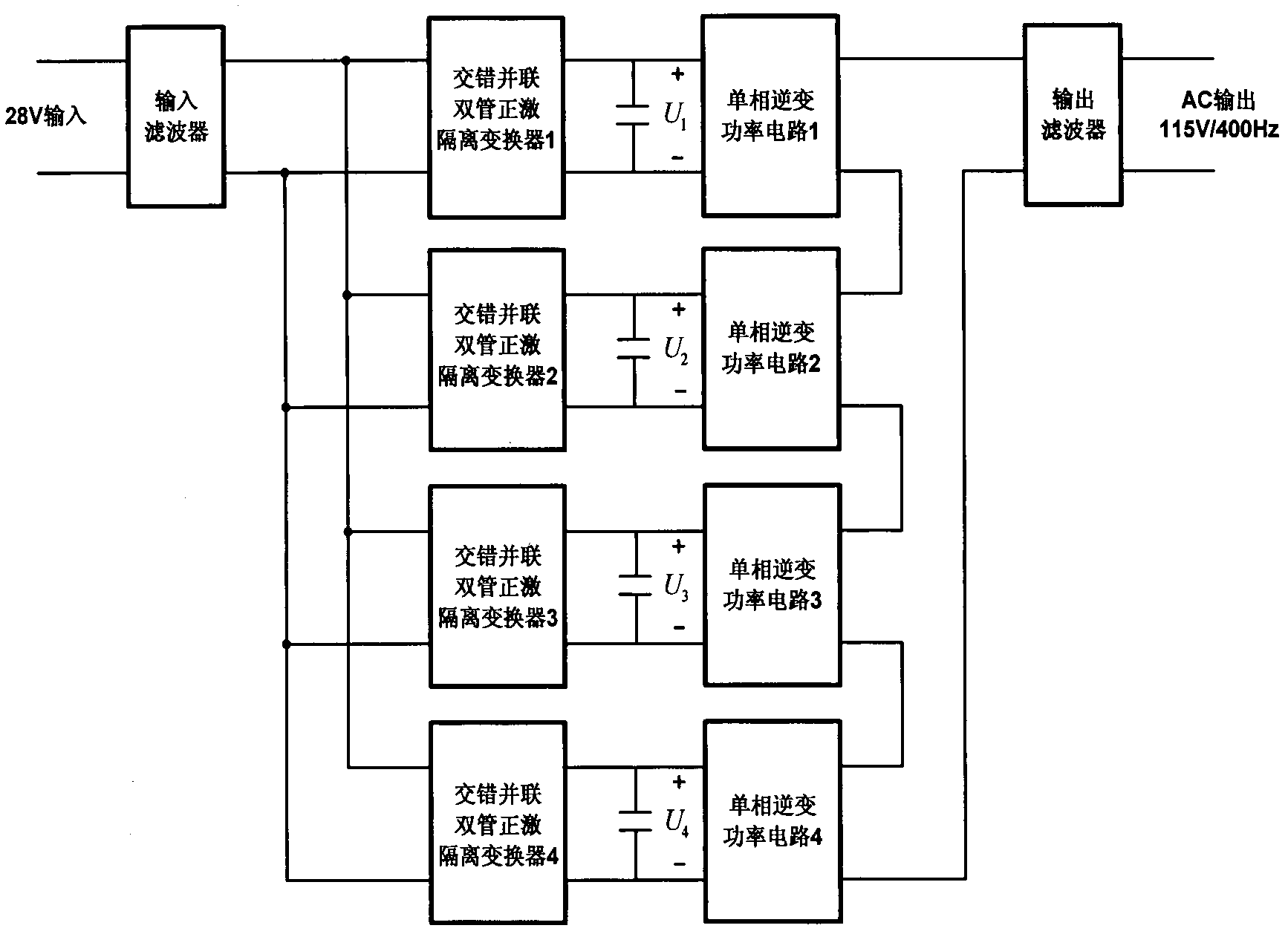
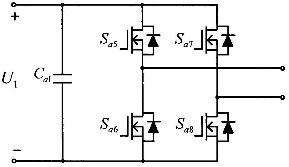
[0021] The block diagram of the main circuit structure of the cascaded time-division variable-order high multi-level static converter in this embodiment is as follows figure 1 As shown, it is characterized in that: the DC / DC converter is composed of four identical double-tube forward isolation converters, the input terminals of the four DC converters are connected in parallel, and the output terminals are isolated and output by four transformers. 1 , U 2 , U 3 , U 4 ; The rear stage is a cascaded inverter composed of four single-phase inverter power circuits and output filter circuits, and its input terminals correspond to the output voltages of the previous four-way DC-DC converters respectively. The output ends of the series are output through the LC filter circuit.

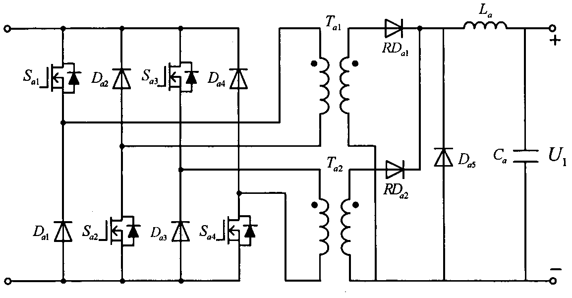
[0022] The front-stage four-way DC / DC converters in this embodiment all adopt the topology of a dual-transistor forward isolation converter. Taking the interleaved parallel dual-transistor forward converter ...


PUM


Abstract

The invention provides a cascade type time-interval variable-order multi-level static converter, which can be modularized; a previous-stage four-way isolation DC-DC (Direct-Current-Direct-Current) converter (1) is connected to a subsequent-stage four-unit cascade inverter (2); a novel time-interval variable-order multi-level control circuit (3) is connected between the previous stage and the subsequent stage; the converter is characterized in that the previous stage is adopted with four ways of mutually independent, staggered and parallel double-tube forward direct-current converters; the subsequent stage is a cascade structure composed of four single-phase H bridges; a carrier phase-shifting frequency-doubling SPWM (Sinusoidal Pulse Width Modulation) technology is adopted; the time-interval variable-order multi-level control circuit is connected between the previous stage and the subsequent stage; the previous stage of the static converter is beneficial to reducing input current ripple and reducing the volume of a filter; the subsequent stage is low in voltage stress of a power switch device, high in circuit modularization degree and low in loss; and, by means of the time-interval variable-order multi-level control circuit, on the premise of not increasing the number of independent sources of the previous stage, the more level number of output can be realized, and the THD (Total Harmonic Distortion) of the harmonic wave is low.

Description

technical field [0001] The invention relates to a cascade type time-divided step-variable high multi-level static converter, which belongs to the power electronic conversion technology. Background technique [0002] In recent years, cascaded multilevel inverters have received extensive attention in various occasions where DC power is converted into AC power. A single-phase / three-phase inverter formed by connecting several basic inverter units in series is called a cascaded inverter. Since the cascaded inverter has a single device with less voltage stress, it is easier to achieve high voltage and large capacity; at the same switching frequency, the output voltage and current waveforms are closer to sine waves, and the harmonic content is low; no clamping diodes and clamping Capacitor, simple structure, easy to modularize and other advantages, and although the overall equivalent switching frequency becomes higher, the switching frequency of each H-bridge unit is reduced, whic...

Claims


Application Information

Patent Timeline
Patent Type & Authority Applications(China)
IPC IPC(8): H02M7/42H02M3/335H02M7/5387
Inventor 许炜秦海鸿叶学俊马婷叶楠叶军
Owner NANJING UNIV OF AERONAUTICS & ASTRONAUTICS
Why Eureka
Try Eureka