Micro-displacement optical test method and device thereof

An optical test and micro-displacement technology, which is applied in the direction of using optical devices, measuring devices, and using optical devices to transmit sensing components, can solve problems such as expensive, complex and large equipment, and achieve error elimination, weight and size reduction, Simple structure and easy effect

Inactive Publication Date: 2008-03-12
SOUTHEAST UNIV
View PDF0 Cites 24 Cited by
  • Summary
  • Abstract
  • Description
  • Claims
  • Application Information

AI Technical Summary

Problems solved by technology

[0010] In the existing micro-displacement and micro-strain test methods, most of the equipment with μm precision is expensive and complic

Method used


Image

  • Micro-displacement optical test method and device thereof
  • Micro-displacement optical test method and device thereof

Examples


Embodiment 1

[0031] A micro-displacement optical test method:

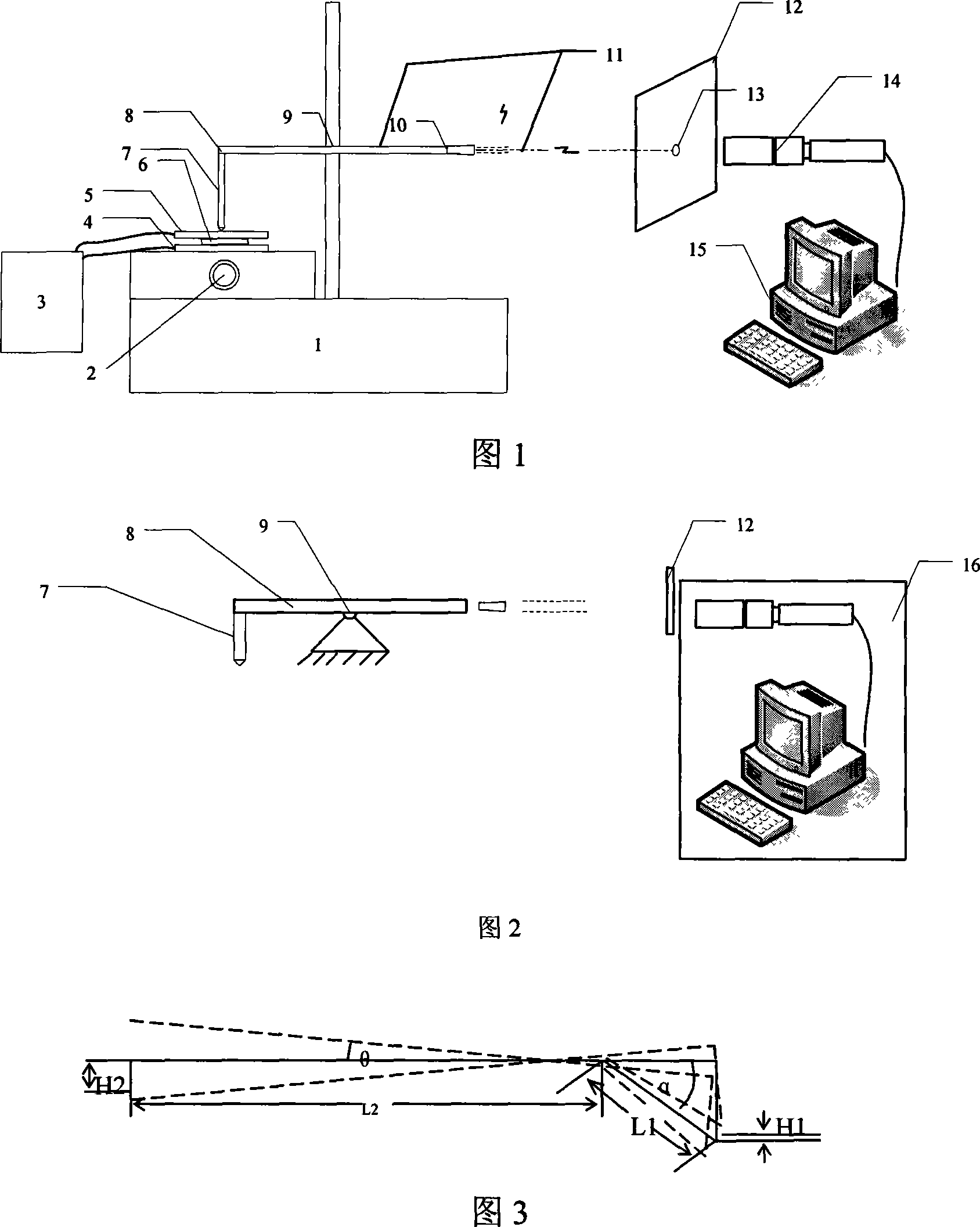
[0032] Step 1: Take the lever, support the lever 9 and make the lever form the short arm 8 and the long arm 11, and set the laser 10 on the long arm 11; take the projection surface 12, place the projection surface 12 in front of the laser 10, and make the The light spot emitted by the laser 10 is projected onto the projection surface 12,

[0033] Step 2 Take a point on the short arm 8 of the lever as the input end of the micro-displacement, input the micro-displacement to be measured from the input end of the micro-displacement, after being enlarged by the lever, an enlarged light spot displacement is generated on the projection surface 12, and then use the light spot displacement The measuring device 16 measures the displacement value of the light spot, and obtains the micro-displacement to be measured through calculation.

[0034] The laser 10 is placed at the end of the long arm 11 so that the laser beam generated by the l...

Embodiment 2

[0036] As shown in Figure 1, a kind of device that realizes above-mentioned micro-displacement optical test method, comprises: light spot displacement measuring device 16, also comprises lever, and this lever is arranged on support 9, uses a point on the short arm 8 of lever as to-be-measured The input end of the micro-displacement is provided with a laser 10 on the long arm 11 of the lever, and a projection surface 12 for displaying the displacement of the light spot is provided in front of the laser 10. The above-mentioned light spot displacement measurement device 16 is used for the displacement of the light spot emitted by the laser 10. Acquisition and calculation of micro-displacement.

[0037] The laser 10 is arranged at the end of the long arm 11 of the lever, and the laser beam generated by the laser 10 is parallel to the lever.

[0038]The end of the lever short arm 8 is used as the input end of the micro-displacement to be measured.

[0039] The present invention al...


PUM


Abstract

The invention relates to a micro-displacement optical testing method and a micro-displacement optical testing device, in particular to a micro-displacement micro-strain testing method and a micro-displacement micro-strain testing device, which adopts the following steps: 1. taking a lever and a projection plane; 2. taking one point on a short arm of the lever as the input end of the micro-displacement, inputting the micro-displacement to be tested from the input end of the micro-displacement, using a light spot displacement measuring device to measure the displacement value of the light spot after enlarging the lever, and gaining the micro-displacement to be tested through the calculation. The invention uses the following devices which comprises the light spot displacement measuring device and the lever, wherein the lever is arranged on a support and takes one point on the short arm of the lever as the input end of the micro-displacement to be tested, a long arm of the lever is provided with a laser, the frontage of the laser is provided with the projection plane for displaying the displacement of the light spot, and the light spot displacement measuring device is used to gain the displacement of the light spot emitted by the laser and calculate the micro-displacement. The invention realizes the purpose of simplifying the structure and making the testing process conveniently operated.

Description

technical field [0001] The invention relates to a micro-displacement and micro-strain testing method and a device thereof, in particular to a micro-displacement optical testing method and a device thereof. Background technique [0002] At present, the methods for measuring micro-deformation usually include interferometry, laser ranging method, capacitance method, differential transformer method, etc. Among them, the capacitance method and the differential transformer method convert the micro-deformation measurement into the electric quantity measurement, and both need to be in contact with the measured surface. Contact is a non-contact measurement. Contact measurement obtains the geometric information of the measured surface by contacting the probe with the measured surface. The measurement accuracy is high, but the measurement efficiency is low and the measurement range is relatively small; non-contact measurement can be divided into laser measurement and CCD visual measur...

Claims


Application Information

Patent Timeline
IPC IPC(8): G01B11/00G01B11/16G01D5/26
Inventor 李建清吴剑锋林保平
Owner SOUTHEAST UNIV
Why Eureka
Try Eureka