Imaging apparatus

Inactive Publication Date: 2005-09-22
SONY CORP
View PDF14 Cites 24 Cited by
  • Summary
  • Abstract
  • Description
  • Claims
  • Application Information

AI Technical Summary

Benefits of technology

[0010] According to the present invention, a variety of electrical circuits, such as control circuits for the panning mechanism and the tilt mechanism, power supply circuit or signal processing circuit for imaging signals, are mounted in a shared fashion on the first wiring board and on the second wiring board, so that the wiring boards may be reduced in size. Consequently,

Problems solved by technology

Thus, with the imaging apparatus, the wiring board is increased in size, and the casing in which to install the wiring board is also increased in size, thus increasing the weight of the overall apparatus.
If the imaging apparatus

Method used


Image

  • Imaging apparatus
  • Imaging apparatus
  • Imaging apparatus

Examples


Example

[0029] Referring to the drawings, an imaging apparatus according to the present invention is hereinafter explained in detail.

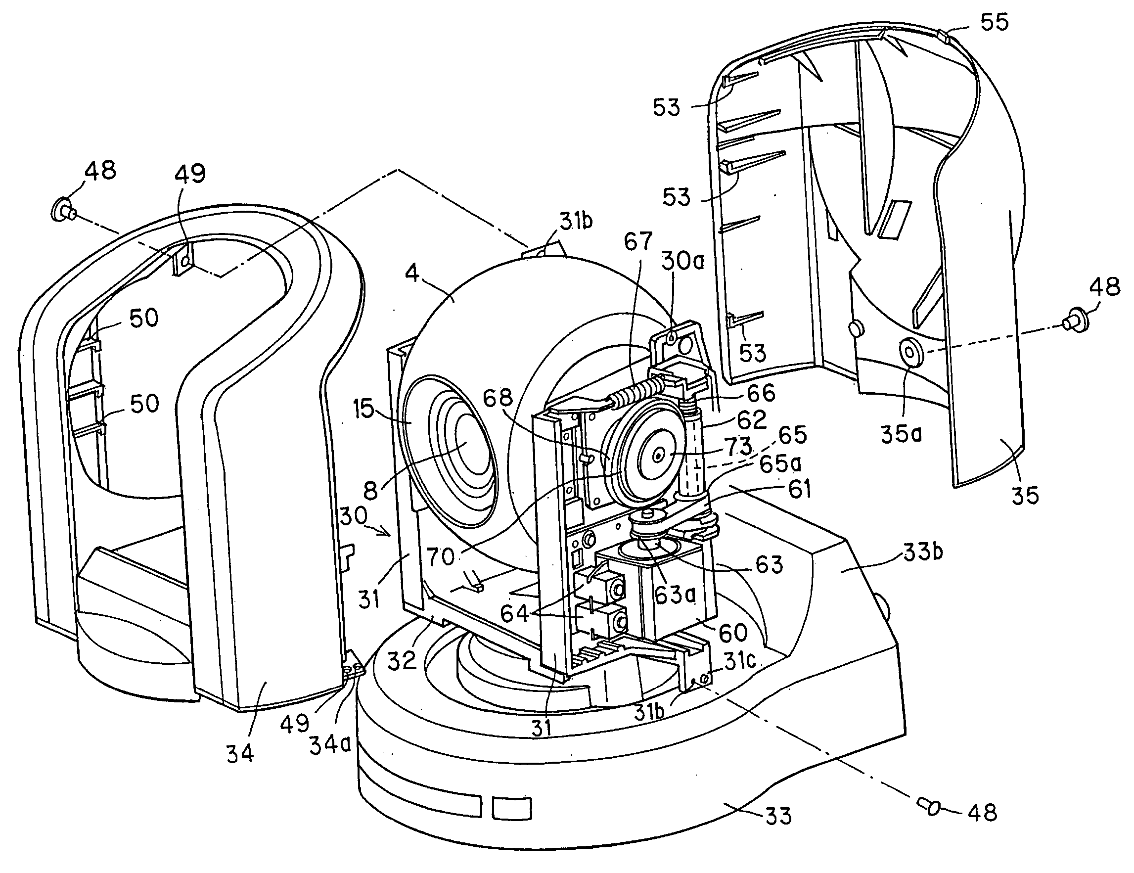
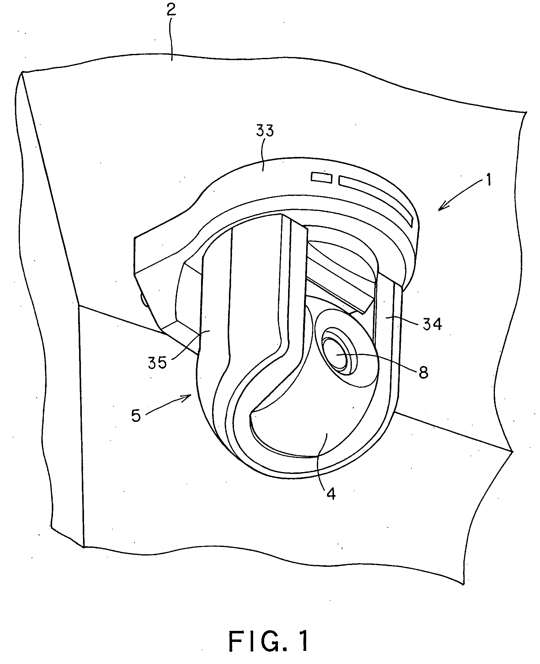
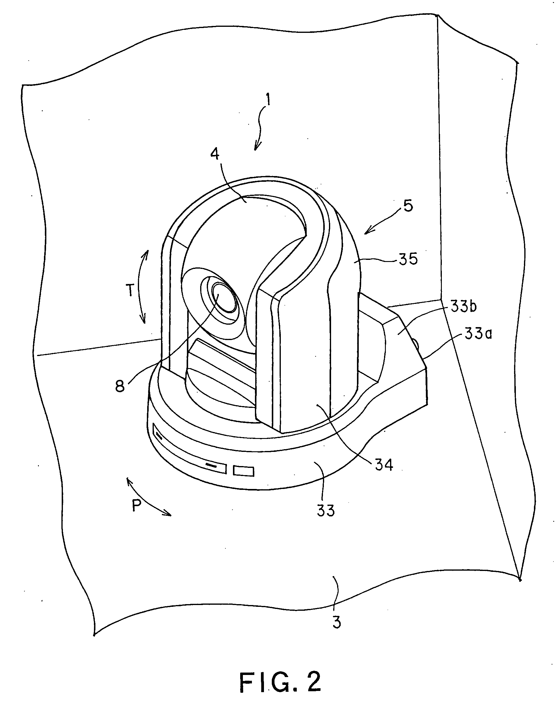
[0030] An imaging apparatus 1 is mounted in an upside-down position on a ceiling 2 of a room, as shown in FIG. 1, or mounted on a floor 3, as shown in FIG. 3, for imaging the state in the room or an outdoor scene. In place of being mounted in an up-and-down position, as shown in FIGS. 1 and 2, the imaging apparatus 1 may also be mounted to an outer wall or an inner wall substantially at right angles thereto. The imaging apparatus 1 includes an imaging unit 4 for imaging the state in a room or an outdoor scene, and a casing 5 for holding the imaging unit 4 therein. The imaging apparatus 1 also includes a tilt mechanism for causing rotation of the imaging unit 4 in the tilt direction and a panning mechanism for causing rotation thereof in the panning direction.

[0031] Referring to FIGS. 3 to 5, the imaging unit 4 is made up by an imaging device 6 and a cover 7 ...


PUM


Abstract

Disclosed is a stationary type imaging apparatus reduced in size and in weight. The imaging apparatus includes an imaging unit 4 for imaging an object and a casing 5 carrying the imaging unit 4 and also carrying a component mounting unit 36 on its bottom for mounting component parts of the imaging apparatus. On the component mounting unit 36, a first wiring board 37 is provided for extending along a bottom plate of the casing 5, and a second wiring board 38 is provided for extending towards the imaging unit 4 in a state separated from the first wiring board 37.

Description

BACKGROUND OF THE INVENTION [0001] 1. Field of the Invention [0002] This invention relates to a stationary type imaging apparatus for imaging the indoor or outdoor state from a fixed position. [0003] This application claims priority of Japanese Patent Application 2004-006135, filed on Jan. 13, 2004, the entirety of which is incorporated by reference herein. [0004] 2. Description of Related Art [0005] A stationary type imaging apparatus, mounted at a preset position, such as on a ceiling or a wall in a room or an outer wall outside the building for imaging the indoor or outdoor state, has an imaging unit enclosed in a casing, mounted on the ceiling or wall, and is mounted on a ceiling or on an upper part of the inner wall of a church or a concert hall, for imaging the state of the Mass in a church or a music concert in a concert hall from an upper point towards an oblique lower area. In such imaging apparatus, in distinction from a monitor imaging device for imaging a preset range of...

Claims


Application Information

Patent Timeline
IPC IPC(8): F16M11/12G03B17/02F16M11/18G03B17/56H04N5/222H04N5/225H04N7/18H05K1/14
CPCF16M11/10F16M11/12F16M11/18F16M11/2014F16M13/027H05K1/144G08B13/19619G08B13/1963G08B13/19632G08B13/19634H04N5/2251F16M2200/041H04N23/50H04N7/18H04N23/00
Inventor AOKI, OSAMUHOSOYA, TAKAMASATAMURA, SHIGERU
Owner SONY CORP
Why Eureka
Try Eureka