Freely rotatable binding for board sports with internal resilience and safety lock

a free-rotation, sports-based technology, applied in the field of sports-based bindings, can solve problems affecting performance especially responsiveness, and achieve the effects of improving responsiveness, quick and smooth return action, and little end vibration action

Inactive Publication Date: 2007-01-11
STEFANIC DANIEL M
View PDF40 Cites 10 Cited by
  • Summary
  • Abstract
  • Description
  • Claims
  • Application Information

AI Technical Summary

Benefits of technology

[0017] In a further embodiment of the invention, instead of a second channel with springs, a Y-shaped channel having a single spring positioned therein and connected at one to the bottom circular plate and at the other end to the binding plate serves to improve responsiveness and return of the binding plate to its home position. The sides of the Y-channel are close to the spring resulting in a quick and smooth return action with very little end vibrational action.

Problems solved by technology

Further, the L-section bushing removes or limits play between the top circular plate and the binding plate, which can affect performance especially responsiveness of the board.

Method used


Image

  • Freely rotatable binding for board sports with internal resilience and safety lock
  • Freely rotatable binding for board sports with internal resilience and safety lock
  • Freely rotatable binding for board sports with internal resilience and safety lock

Examples


Embodiment Construction

)

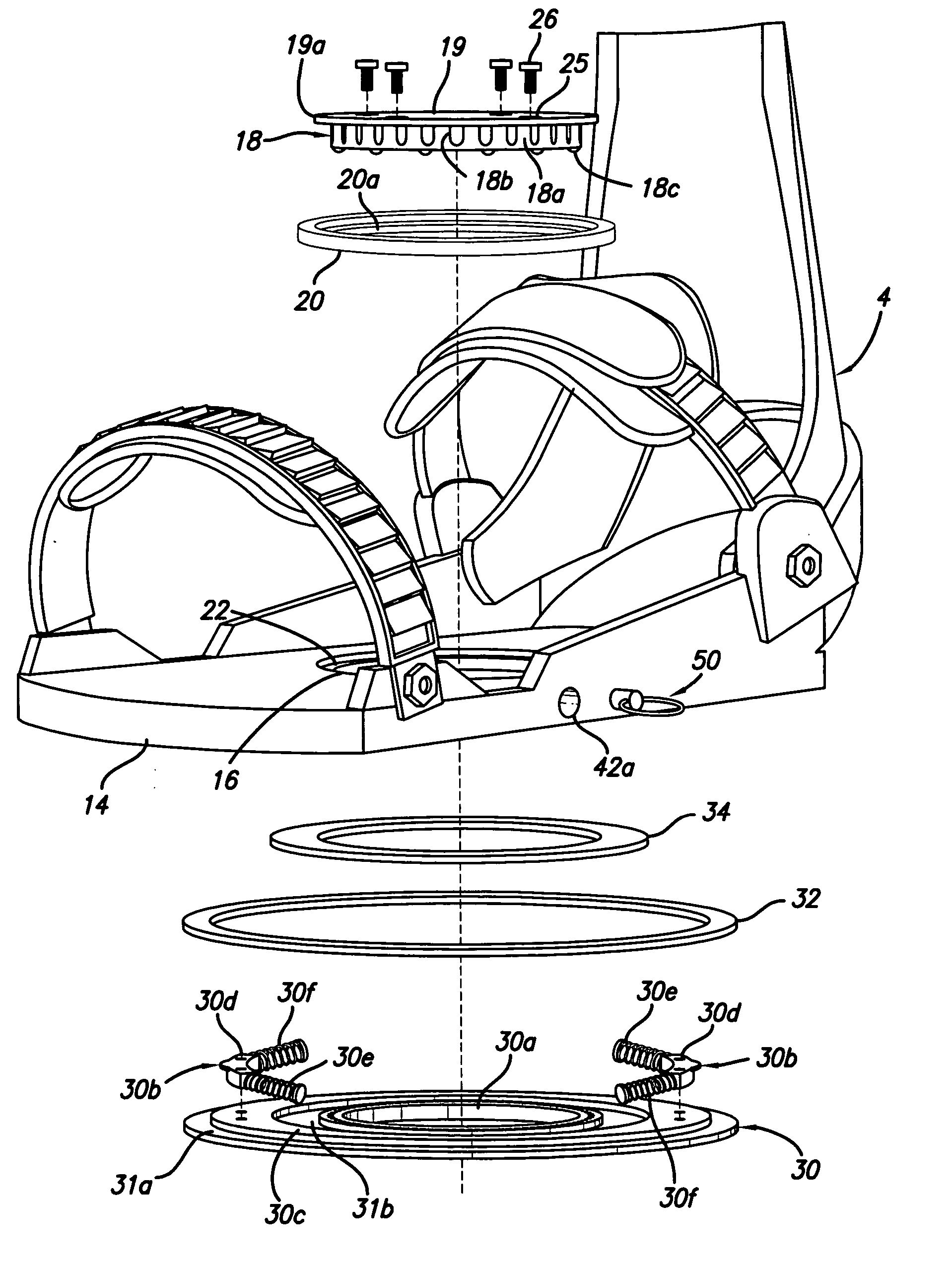
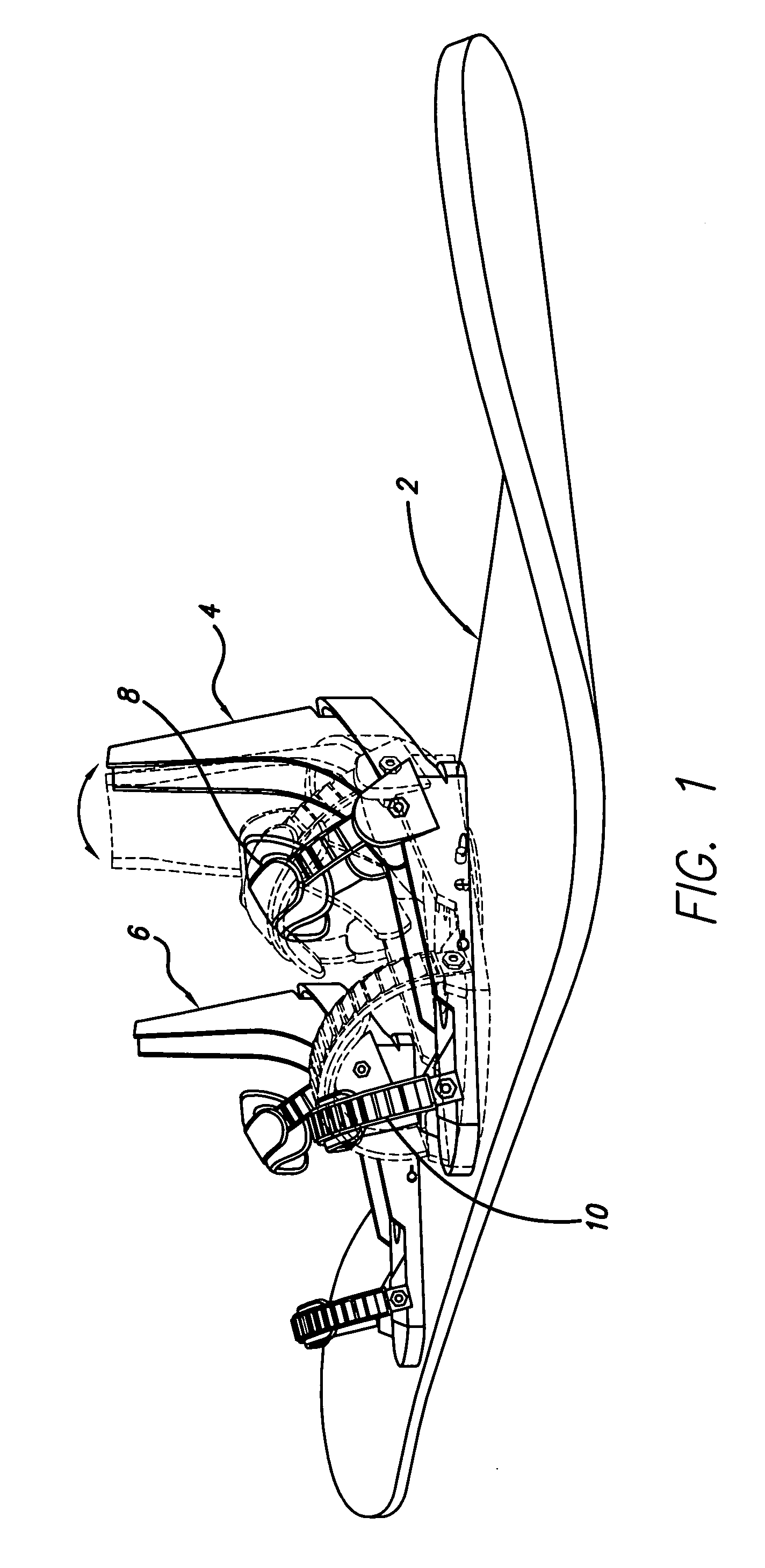
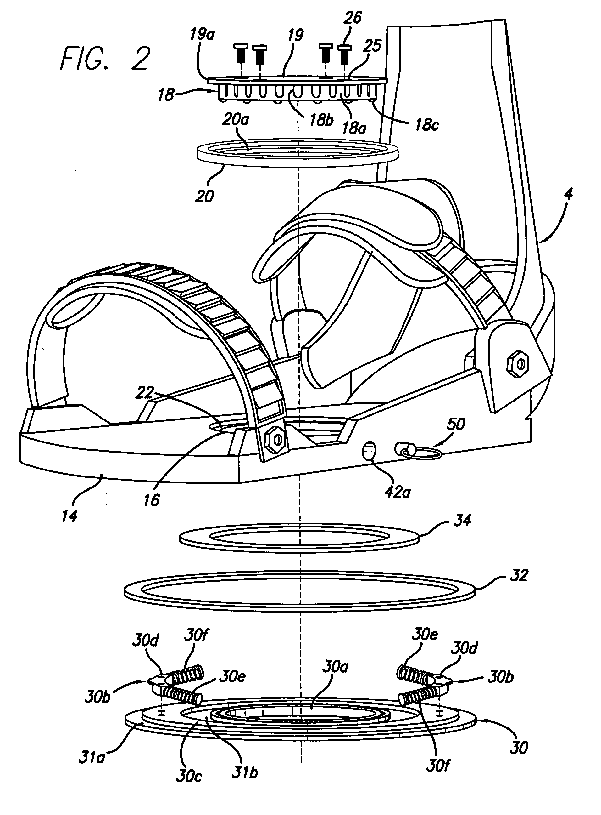
[0030] With reference to the perspective view of a snowboard 2 having a front foot binding assembly 4 (left foot in the position shown, but it can be the right foot) and a rear foot binding assembly 6 (right foot in the position shown).

[0031] A snow boarder will put his or her feet having boots thereon into the binding assemblies 4, 6 and close straps 8, 10 for a snug secure fit. The rear binding assembly has two straps also.

[0032] The more rigid the connection from the board to the binding to the user's feet, the more responsive the board will be to the user's motion. In one embodiment of the invention, the front binding assembly is rotatable clockwise or counterclockwise about a vertical axis through the binding or bottom plate. FIG. 1 further shows binding assembly 4 in phantom after it has rotated to the left with respect to a horizontal axis running the length of binding plate 4 (toe end of binding rotated out of the page). As explained in detail below, in a preferred embodi...


PUM


Abstract

A binding for a snowboard or wakeboard is rotatable in a horizontal plane along the board, during use. Preferably, the binding is biased to a preset or original or home position. The biasing force is adjustable and generally is set in a range that allows movement during actual use of the board, requiring more than casual effort to change the angle but less than extreme effort to change the angle. In one embodiment, there are two arcuate channels in the bottom of a binding plate. In each channel there is a spring assembly having a central block fixed to a circular bottom plate. The block has a spring on each side, which springs are also in the channel. As a user rotates his foot in the binding, the binding plate rotates on the circular bottom plate, compressing the one of the springs in each channel. In a most preferred embodiment, there is a top circular plate above the binding plate, and the binding plate has a circular seat for an annular L-section bushing which seats in the seat, and mates with the top circular plate. This L-section bushing is preferably plastic, and serves multiple purposes. It not only protects against metal to metal contact where the top circular plate is metal, but also seals the assembly against snow, ice and water, even if the top circular plate is made of plastic. Further, the L-section bushing removes or limits play between the top circular plate and the binding plate, which can affect performance especially responsiveness of the board. In another embodiment, a Y-shaped channel having a single spring positioned therein is used instead of a second set of springs.

Description

BACKGROUND OF THE INVENTION [0001] 1. Field of the Invention [0002] The present invention relates to a binding for a sports board that is rotatable during use, and more particularly to sports boards' bindings such as for a snow board or wakeboard which bindings that are rotatable during use and biased to a preset position. [0003] 2. Description of the Related Art [0004] Snow boarding has grown tremendously in popularity over the last two decades. Part of its growth has resulted in a variety of snow board competitions, such as freestyle, jumping, racing, and other competitions. Unlike snow skiing where the skier's feet are separately movable because there is a ski for each foot, the snow boarder's feet are secured in bindings that are fixed to one board. The rear or back foot is usually at an angle of about ninety degrees to the length of the board (front to rear axis of the board). The front or lead foot is usually at an angle of about forty five to sixty degrees to the length of th...

Claims


Application Information

Patent Timeline
Patent Type & Authority Applications(United States)
IPC IPC(8): B62B13/00
CPCA63C10/04A63C10/24A63C10/18A63C2203/54
Inventor STEFANIC, DANIEL M.
Owner STEFANIC DANIEL M
Why Eureka
Try Eureka