Measurement bias tee

a bias tee and measurement technology, applied in the field of bias tees, can solve the problems of introducing its own measurement errors, challenging the accuracy of and/or sensitive measurement,

Active Publication Date: 2007-01-11
KEITHLEY INSTRUMENTS INC
View PDF3 Cites 8 Cited by
  • Summary
  • Abstract
  • Description
  • Claims
  • Application Information

AI Technical Summary

Problems solved by technology

Unfortunately, the bias tee 10 introduces its own measurement errors, for example, leakage and stray capacitances.
This particularly creates challenges in making very accurate and / or very sensitive measurements (e.g., pico- and femto-ampere measurements).

Method used


Image

  • Measurement bias tee
  • Measurement bias tee
  • Measurement bias tee

Examples


Embodiment Construction

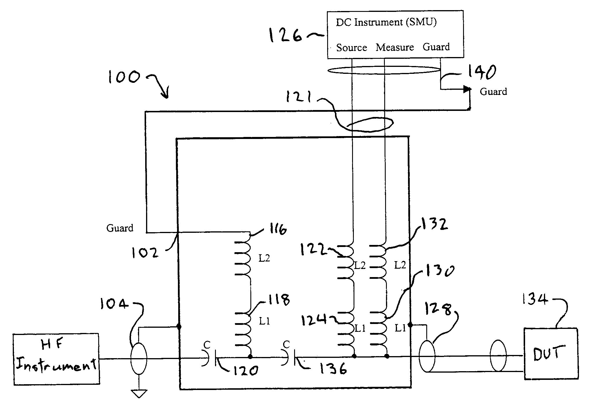
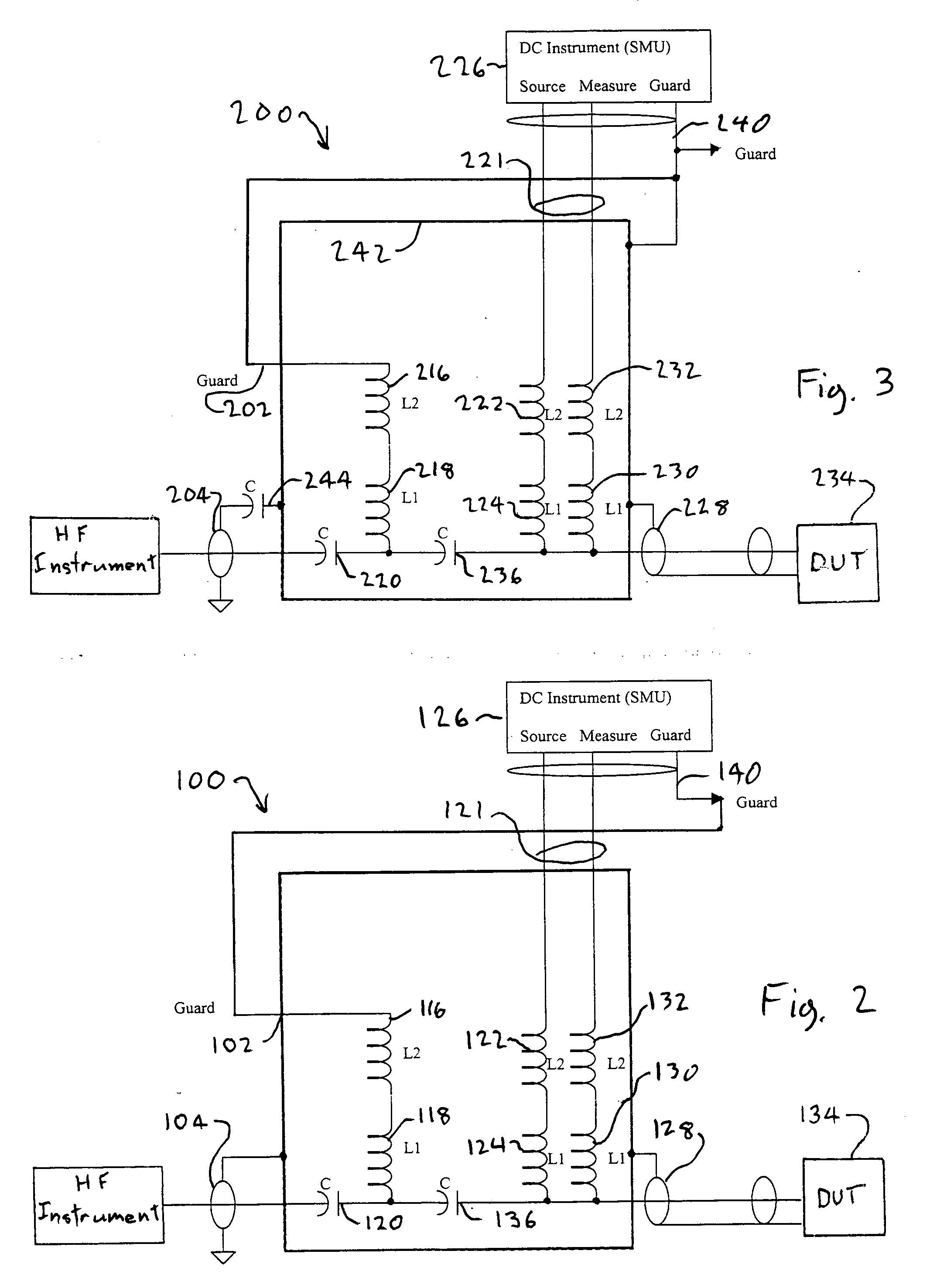
[0011] Referring to the example of FIG. 2, a bias tee 100 includes a guard input 102. The guard input 102 is connected to the HF port 104 of the bias tee 100 by an impedance network formed from the inductors 116, 118 and the capacitor 120. The DC instrument 126 is connected to the DC port 121 of the bias tee 100. The inductors 122, 124 connect the source output of the DC instrument 126 to the output port 128 of the bias tee 100. The inductors 130, 132 connect the measure input of the instrument 126 to the output port 128.

[0012] In operation, the output port 128 applies both DC and HF to the DUT 134. The capacitor 136 allows HF to travel to the port 128 and the inductors 122, 124, 130, 132 block HF from the instrument 126.

[0013] The capacitor 120 blocks DC from the guard input 102 from entering the instrument 126 and the inductors 116, 118 block HF from the guard input 102.

[0014] The guard output 140 of the DC instrument 126 is typically driven at a voltage equal to the forcing vo...


PUM


Abstract

A bias tee for connecting a measurement device to a DUT, where the measurement device has a guard output, includes a DC port; a HF port; and a measurement port. The HF input port is guarded with the guard output during operation of the bias tee.

Description

BACKGROUND OF THE INVENTION [0001] The present invention relates to the measurement of electrical signals and, in particular, to bias tees used therein. [0002] The use of bias tees in measurements is well-known. Referring to FIG. 1, a prior art bias tee 10 is used to connect a DC instrument 12. (e.g, a source measurement unit) and a high frequency (HF) instrument 14 to a device under test 16 (DUT). The HF instrument 14 may be, for example, a combination RF signal generator and measurement device. It should be noted that the bias tee 10 can also be used in the case of pulses as opposed to radio frequency signals per se, the frequency content of typical interest being similar. [0003] The typical purpose of the bias tee 12 is to allow the simultaneous application of HF and low frequency (e.g., DC) signals to the DUT 16. At the same time, DC signals are blocked from the instrument 14 and HF signals are blocked from the instrument 12. For example, the DC signals may serve to bias the DUT...

Claims


Application Information

Patent Timeline
Patent Type & Authority Applications(United States)
IPC IPC(8): G01R27/26
CPCG01R27/04G01R31/2889G01R31/2844
Inventor KNAUER, WILLIAM
Owner KEITHLEY INSTRUMENTS INC
Why Eureka
Try Eureka