Imaging apparatus and imaging method

a technology of imaging apparatus and image, applied in the field of imaging apparatus and imaging method, can solve the problems of deteriorating shake correction accuracy, inability to accurately match frames, and inability to shake or subject shake within one frame,

Inactive Publication Date: 2007-01-11
FUJIFILM CORP +1
View PDF1 Cites 66 Cited by
  • Summary
  • Abstract
  • Description
  • Claims
  • Application Information

AI Technical Summary

Benefits of technology

[0008] A first aspect of the invention provides an imaging apparatus including the function of conducting automatic exposure control and the function of conducting shake correction with respect to digital image data acquired by an image pickup unit, the imaging apparatus comprising: a determining unit that determines whether or not the shake c

Problems solved by technology

However, even when the apparatus proposed in JP-A No. 11-98420 is used, shake or subject-shake within one frame occurs when the shutter speed is low at the time of shake correction when conducting moving image imaging.
Moreover, assuming that this shake correction is condu

Method used


Image

  • Imaging apparatus and imaging method
  • Imaging apparatus and imaging method
  • Imaging apparatus and imaging method

Examples


first embodiment

[0054] Next, the action of the first embodiment will be described.

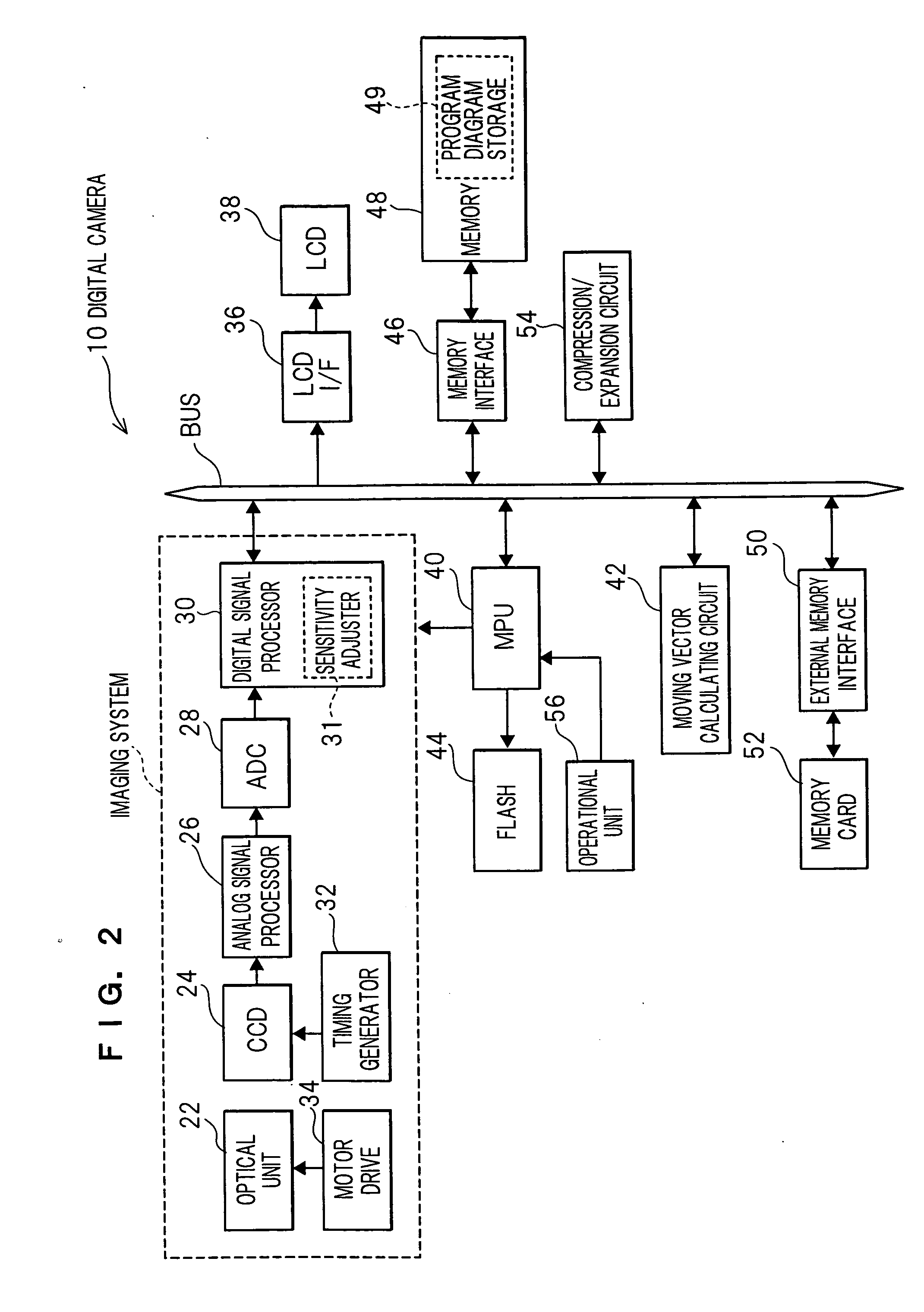
[0055] First, the CCD 24 conducts imaging via the optical unit 22 and sequentially outputs to the analog signal processor 26 analog signals of red, green and blue representing the subject image. The analog signal processor 26 administers analog signal processing such as correlated double sampling with respect to the analog signals inputted from the CCD 24, and then sequentially outputs the processed analog signals to the ADC 28.

[0056] The ADC 28 converts the analog signals of red, green and blue inputted from the analog signal processor 26 to 12-bit signals of red, green and blue (digital image data), and then sequentially outputs the digital image data to the digital signal processor 30. The digital signal processor 30 accumulates in its line buffer the digital image data sequentially inputted from the ADC 28, and directly stores the digital image data in a predetermined region of the memory 48.

[0057] The digital i...

second embodiment

[0071] Next, a digital camera 10 according to the invention will be described.

[0072] Reference numerals that are the same as those in the first embodiment will be given to portions having basically the same configuration as those in the first embodiment, and description of those portions will be omitted.

[0073] The digital camera 10 of the second embodiment is equipped with the function of increasing the shutter speed by raising the ISO sensitivity when the shake correction mode has been set. The action of the portion relating to this function will be described in detail in accordance with the flow chart of FIG. 5.

[0074] First, it is determined in step 150 by the determination of the MPU 40 whether or not the mode switch 56C has been rotated and set to the shake correction mode. When the mode switch 56C has been set to the shake correction mode and the determination in step 150 is YES, then the processing moves to step 152, and when the determination in step 150 is NO, then the pro...

third embodiment

[0085] Next, a digital camera 10 according to the invention will be described.

[0086] Reference numerals that are the same as those in the first embodiment will be given to portions having basically the same configuration as those in the first embodiment, and description of those portions will be omitted.

[0087] The third embodiment is one where the mode is set to a shutter speed priority mode during the shake correction mode.

[0088] As shown in FIG. 6, the digital camera 10 is disposed with a shutter speed detecting unit 58 that measures the shutter speed. The shutter speed detecting unit 58 is configured to receive from the timing generator 32 a timing signal for driving the CCD 24 and to measure the shutter speed on the basis of the exposure time of the CCD 24.

[0089] In the third embodiment, the digital camera 10 includes a function where the shutter speed is maintained at a speed equal to or greater than the shake limit shutter speed as a result of the shutter speed detecting un...


PUM


Abstract

An imaging apparatus includes the functions of conducting automatic exposure control and of conducting shake correction with respect to digital image data acquired by an image pickup unit. The imaging apparatus includes: a determining unit that determines whether or not the shake correction is being implemented; and a switching unit which, when it has been determined by the determining unit that the shake correction is being implemented, switches the shutter speed such that the shutter speed is raised in comparison to when it has been determined by the determining unit that the shake correction is not being implemented. An imaging method determines whether or not the shake correction is being implemented, and when it has been determined that the shake correction is being implemented, switches the shutter speed such that the shutter speed is raised in comparison to when it has been determined that the shake correction is not being implemented.

Description

CROSS-REFERENCE TO RELATED APPLICATION [0001] This application claims priority under 35 USC 119 from Japanese Patent Application No. 2005-200457, the disclosure of which is incorporated by reference herein. BACKGROUND OF THE INVENTION [0002] 1. Field of the Invention [0003] The present invention relates to an imaging apparatus and an imaging method, and in particular to an imaging apparatus and an imaging method that include the function of conducting automatic exposure control and the function of conducting shake correction with respect to digital image data acquired by an image pickup unit. [0004] 2. Description of the Related Art [0005] Conventionally, there has been technology that electronically conducts shake correction when a moving image is picked up. As this type of technology, Japanese Patent Application Publication (JP-A) No. 11-98420 proposes an electronic shake correction apparatus configured to prevent the deterioration of correction performance resulting from changes ...

Claims


Application Information

Patent Timeline
IPC IPC(8): G03B17/00
CPCG03B17/02H04N5/23248H04N5/23254H04N2101/00H04N5/2327H04N5/23293H04N5/2353H04N5/23258H04N23/684H04N23/6811H04N23/68H04N23/6812H04N23/634H04N23/631H04N23/73
Inventor ITO, TAKEHIKO
Owner FUJIFILM CORP
Why Eureka
Try Eureka