Cell phone and cordless phone with inverted keypad and display arrangement and slanted rows of buttons on keypad

a technology of keypad and display arrangement, which is applied in the direction of substation equipment, electrical equipment, telephone set construction, etc., to achieve the effect of convenient dialing, less strain on the thumb, and convenient us

Inactive Publication Date: 2007-01-11
MIXON JERRY
View PDF0 Cites 13 Cited by
  • Summary
  • Abstract
  • Description
  • Claims
  • Application Information

AI Technical Summary

Benefits of technology

[0007] This invention discloses a cell phone or cordless phone with a significant alteration of the standard face layout by inverting the arrangement of the keypad and the display, and by slanting the rows of buttons or keys on the keypad. Such an arrangement makes the cell phone or cordless phone easier to use and less straining for the thumb when dialing or otherwise accessing the keypad with the thumb of the same hand holding the phone. With the keypad located above the display, the user's thumb will tend to be in a more natural and relaxed position while dialing, and a slanted arrangement of the keys that follows the sweep of the thumb makes dialing easier, rather than following a rigid vertical and horizontal line arrangement as with the conventional phone layout.
[0008] Presently, no hand-held type of cell phone or cordless phone offers purchasers a choice of location of keypad and display as described in this application. Since the conventional lower location of the keypad leads to an awkward reach with the thumb, some people turn the telephone upside down to dial. But they then have to read the display and key numbers upside down; moreover, after the call is connected, they have to return the cell phone to the original position in order to speak to the microphone and hear through the earpiece. Therefore, given a choice, it is very likely that many people would prefer to use a cell phone or cordless phone with the locations of the keypad and LCD display reversed in order to reduce the risk of tendon fatigue and long-term damage.

Problems solved by technology

Since the conventional lower location of the keypad leads to an awkward reach with the thumb, some people turn the telephone upside down to dial.

Method used


Image

  • Cell phone and cordless phone with inverted keypad and display arrangement and slanted rows of buttons on keypad
  • Cell phone and cordless phone with inverted keypad and display arrangement and slanted rows of buttons on keypad
  • Cell phone and cordless phone with inverted keypad and display arrangement and slanted rows of buttons on keypad

Examples


first embodiment

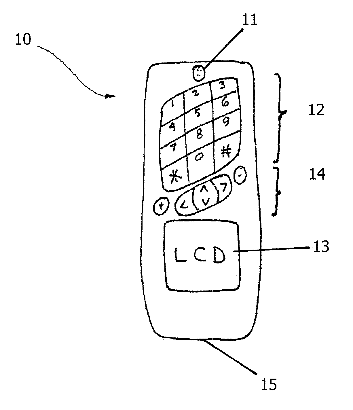
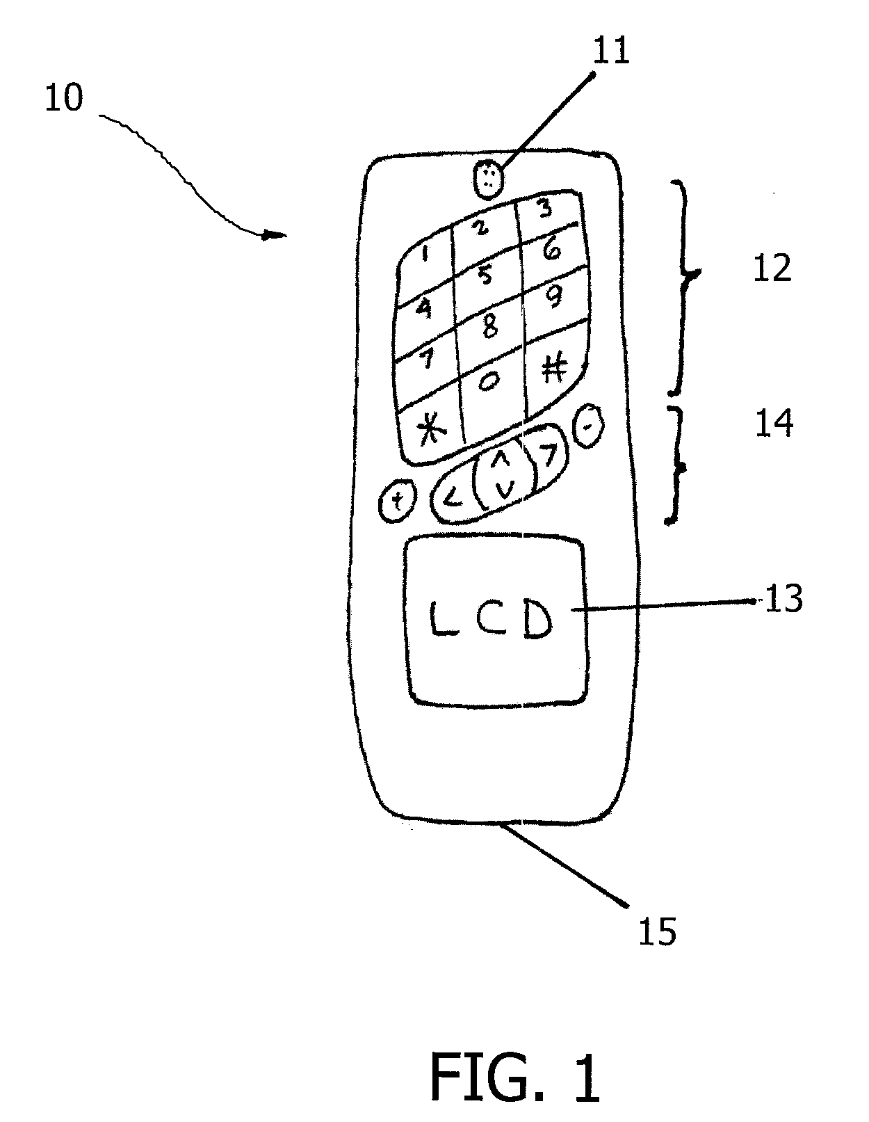
[0015]FIG. 1 is a schematic of a cell phone 10 according to the present invention, which comprises an earpiece 11 at a top end of the phone 10, a keypad 12 below the earpiece 11, a microphone 15 at a bottom end of the phone 10, and a display 13 above the microphone 15 and below the keypad 12. Furthermore, a plurality of function keys or soft keys 14 are disposed between the keypad 12 and the display 13. In FIG. 1, the keypad 12 is above the display 13. In contrast, a conventional cell phone (not shown) with a keypad and display has the display above the keypad. Like a standard phone keypad, the keypad 12 shown in FIG. 1 consists of 12 keys in four rows for entering numbers 1-9, asterisk sign (*), number 0, and pound sign (#). However, the keypad 12 is different from a standard phone keypad in that the rows of keys are slanted upward from left to right.

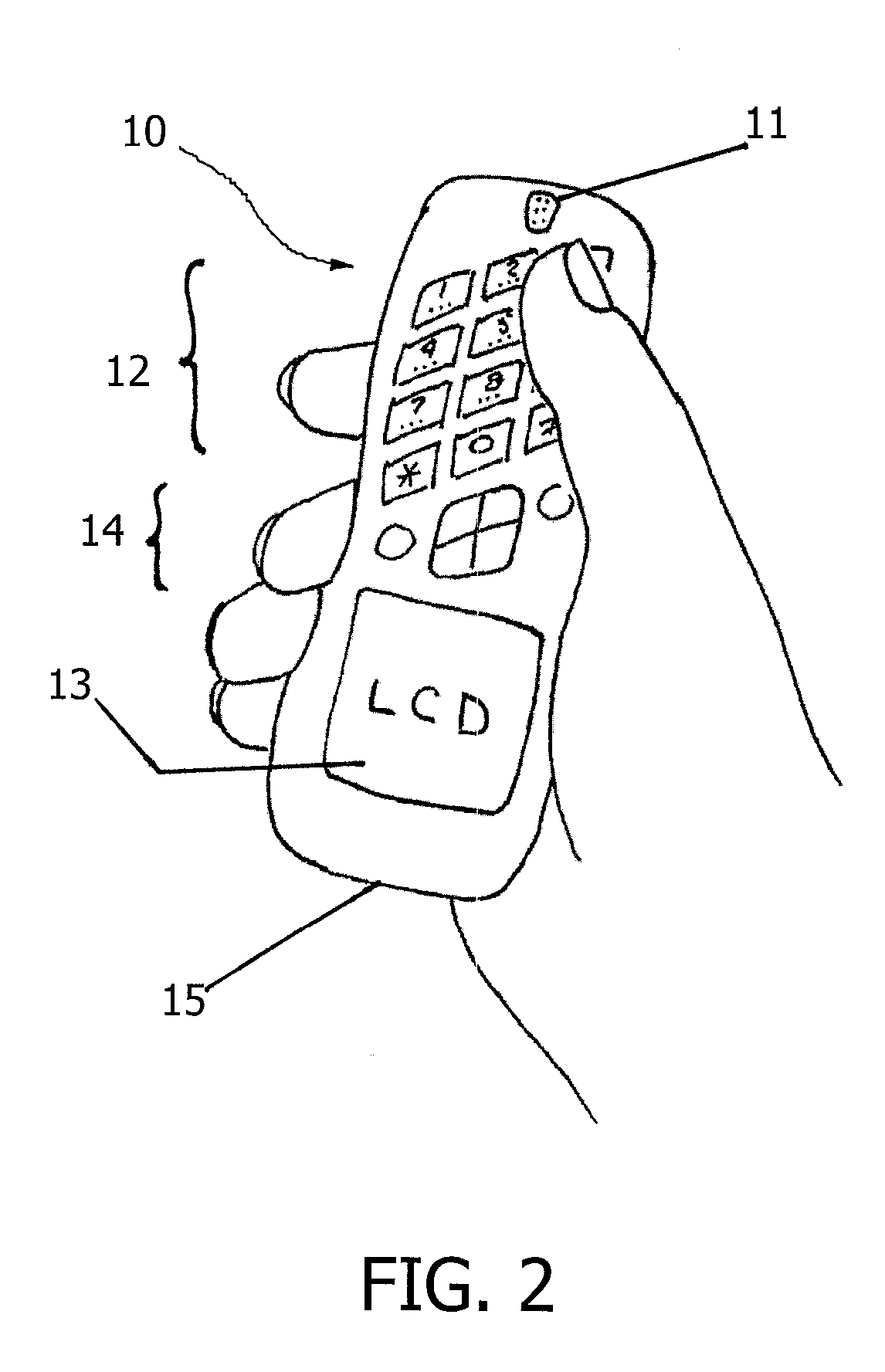
[0016]FIG. 2 illustrates a cell phone 10 in the hand to demonstrate the inverted arrangement of the face layout and the more natural ...

second embodiment

[0017]FIG. 3 is a schematic of a hinged cell phone 20 according to the present invention. The hinged cell phone 20 comprises a base portion 21 and a flap portion 22 hinged at one end to the base portion 21, wherein a display 13 and a microphone 15 are disposed at the base portion 21 whereas the keypad 12 is located at the flap portion 22 below the earpiece 11. Therefore, when the flap portion 22 of the phone 20 is opened (or raised) for dialing, the keypad 12 is located at the top and the display 13 is at the bottom. In contrast, a conventional hinged cell phone (not shown) has the display at the top and the keypad at the bottom.

[0018]FIG. 4 illustrates a hinged cell phone 20 in the hand to demonstrate the inverted arrangement of face layout and the more natural lay of the thumb on the keys and the better grip that results from not having to cradle the unit on the fingers (as is necessary when reaching down with the thumb on conventional units). FIG. 4 also illustrates the relative ...

third embodiment

[0019]FIG. 5 is a schematic of a cordless phone 30 according to the present invention, wherein the keypad 12 is located at the top and the display 13 is at the bottom. In contrast, the typical conventional cordless phone (not shown) has the keypad at the bottom and the display at the top.

[0020] In summary, placing the keypad 12 at the top of the unit and the display 13 at the bottom makes it easier for the thumb to navigate around the keypad 12 and press the keys. Additionally, the typical hand-held phone is often designed to have the widest part of the phone in the area of the LCD display, and putting the LCD display at the bottom of the unit instead of at the top puts the widest part of the unit in the palm. Consequently, a better grip can be maintained on the phone while dialing.

[0021] None of the figures above are intended to dictate the location or order of numbers, letters, nor symbols on the keys or buttons. But the arrangement of buttons or keys in slanted rows to accommoda...


PUM


Abstract

Hand-held telephones (i.e., cell phones or cordless phones) with its keypad and display in inverted (from customary layout) positions and with a slanted keypad arrangement are disclosed in this application. Such a revision of the face layout of this type of telephone allows the user to dial or access the keypad with the thumb of the hand holding the phone with relative ease and with better ergonomics compared to the conventional phone face layout.

Description

CROSS-REFERENCE TO RELATED APPLICATIONS [0001] This application claims the benefit of U.S. Provisional Application No. 60 / 595,453, which was filed Jul. 7, 2005 and is now pending.BACKGROUND OF THE INVENTION [0002] 1. Field of the Invention [0003] The present invention relates generally to hand-held phones with a nontraditional face layout and, more particularly, to a cell phone or cordless phone with keypad and LCD display inverted from the customary layout and with keys on the keypad arranged in a slanted pattern instead of the customary arrangement of vertical and horizontal lines. [0004] 2. Description of the Related Art [0005] The conventional arrangement of the face of hand-held phones, such as cell and cordless phones, has the LCD display located at the upper part and the keypad of buttons located on the lower part. Although hand-held phone units were originally conceived to be held with one hand and dialed with fingers of the other hand, but in actual practice it has become c...

Claims


Application Information

Patent Timeline
Patent Type & Authority Applications(United States)
IPC IPC(8): H04B1/38
CPCH04M1/0216H04M1/23H04M1/0279
Inventor MIXON, JERRY
Owner MIXON JERRY
Why Eureka
Try Eureka