Skeletal Stabilization Implant

a stabilization implant and skeletal technology, applied in the field of skeletal implants, can solve the problems of chronic back problems, persistent pain, pain and disability of a large segment of the population,

Inactive Publication Date: 2007-01-11
ZIMMER SPINE INC
View PDF23 Cites 185 Cited by
  • Summary
  • Abstract
  • Description
  • Claims
  • Application Information

AI Technical Summary

Problems solved by technology

Chronic back problems cause pain and disability for a large segment of the population.
In many cases, chronic back problems are caused by intervertebral disc disease.
When an intervertebral disc is diseased, the vertebrae between which the disc is positioned may be inadequately supported, resulting in persistent pain.

Method used


Image

  • Skeletal Stabilization Implant
  • Skeletal Stabilization Implant
  • Skeletal Stabilization Implant

Examples


Embodiment Construction

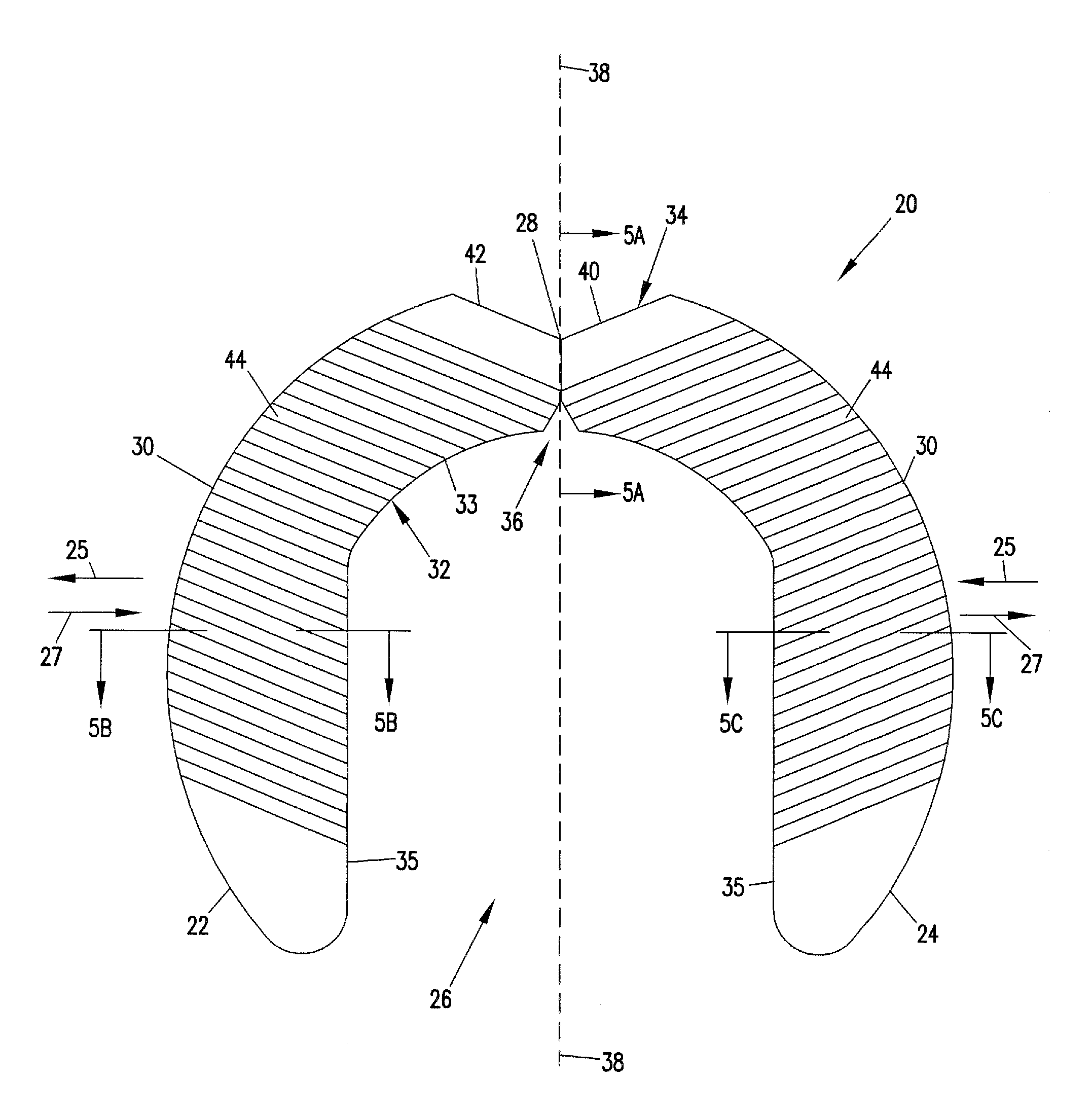
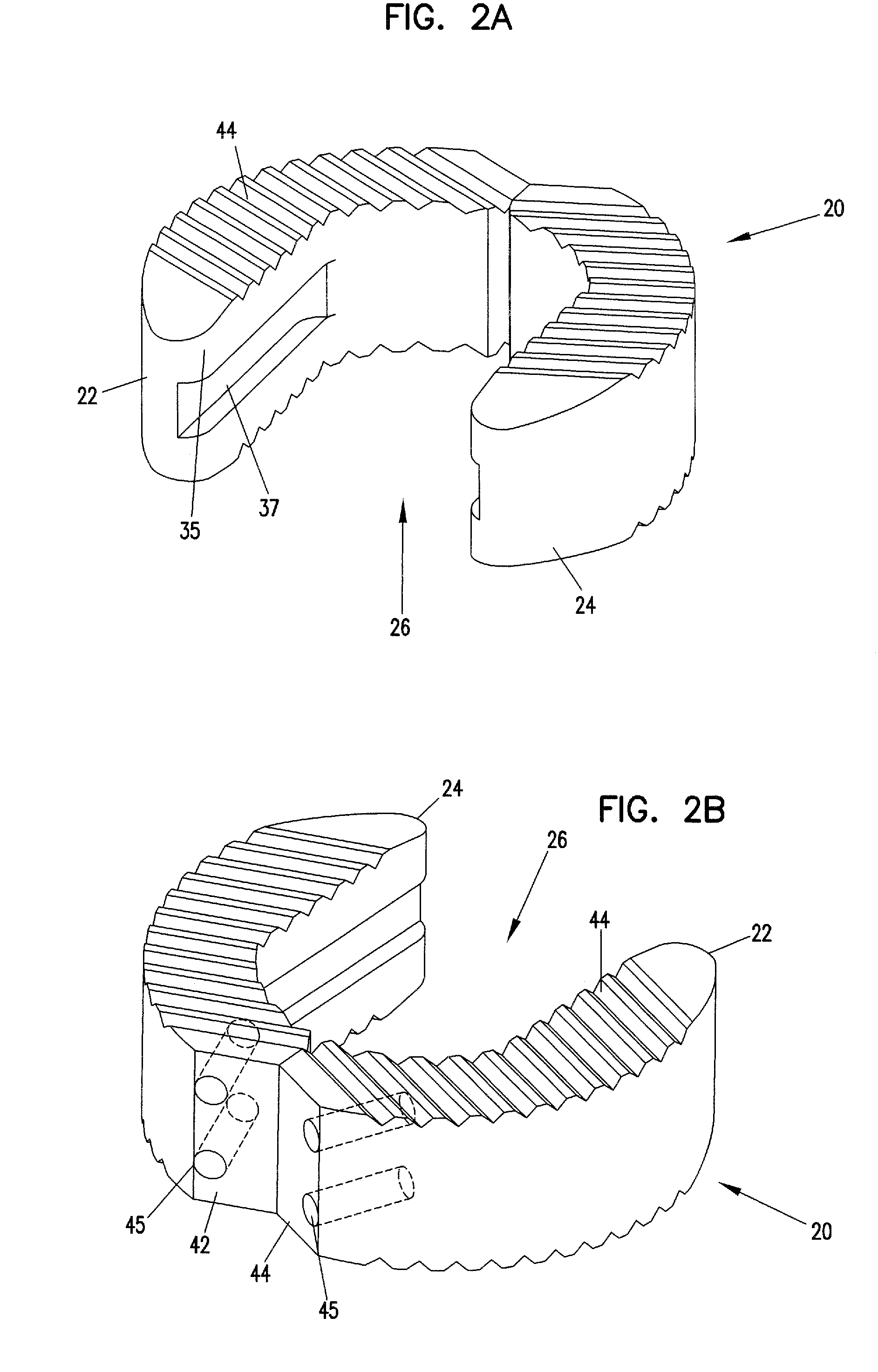
[0023] The present invention is directed to skeletal implants, skeletal implant kits and methods for placing implants between bones desired to be fused. It is preferred for the implants to be used for vertebral / spinal applications such as fusing cervical, thoracic and / or lumbar intervertebral joints. In the case of fusing an intervertebral joint, implants in accordance with the principles of the present invention can be implanted using an anterior, posterior or postero-lateral approach to the patient's vertebrae.

[0024] As used herein, an “implant” includes any implant suitable for facilitating fusion between adjacent bones and includes implants prepared from known implant materials including, non-bone material such as titanium, stainless steel, porous titanium, bio-glass, calcium phosphate, ceramic, carbon fiber-based polymers, biodegradable and polymers. However, it is preferred for implants in accordance with the principles of the present invention to be derived from natural bone...


PUM


Abstract

A spinal implant is described in this disclosure. The implant includes first and second pieces separated by a controlled break location. Spinal implant kits having multiple spinal implant pieces derived from a common source also are disclosed.

Description

[0001] This application claims priority to U.S. Provisional application 60 / 325,804, filed Sep. 28, 2001.FIELD OF THE INVENTION [0002] The present invention relates generally to skeletal implants. More particularly, the present invention relates to implants for stabilizing intervertebral joints. BACKGROUND OF THE INVENTION [0003] Chronic back problems cause pain and disability for a large segment of the population. In many cases, chronic back problems are caused by intervertebral disc disease. When an intervertebral disc is diseased, the vertebrae between which the disc is positioned may be inadequately supported, resulting in persistent pain. Stabilization and / or arthrodesis of the intervertebral joint can reduce the pain and debilitating effects associated with disc disease. [0004] Spinal stabilization systems and procedures have been developed to stabilize diseased intervertebral joints and, in some cases, to fuse the vertebrae that are adjacent the diseased joint space. Most fusi...

Claims


Application Information

Patent Timeline
Patent Type & Authority Applications(United States)
IPC IPC(8): A61F2/44A61B19/00A61B19/02A61F2/00A61F2/28A61F2/30A61F2/46
CPCA61B19/44A61F2250/0085A61F2/0095A61F2/3094A61F2/442A61F2/4455A61F2/4611A61F2002/2825A61F2002/2839A61F2002/30131A61F2002/30153A61F2002/30168A61F2002/30324A61F2002/30561A61F2002/3071A61F2002/30785A61F2002/3082A61F2002/30828A61F2002/30879A61F2002/30892A61F2002/30925A61F2002/3097A61F2002/30975A61F2002/448A61F2002/4627A61F2002/4649A61F2230/0013A61F2230/0019A61F2230/0043A61F2250/0036A61B2019/0267A61B90/90A61B2050/314
Inventor BANICK, CHISTOPHER M.DANT, JACK A.HANSON, DAVID A.HOUFBURG, RODNEY L.
Owner ZIMMER SPINE INC
Why Eureka
Try Eureka