Relay valve for brake system of railway vehicle

A technology for braking systems and rail vehicles, applied in the field of relay valves for rail vehicle braking control systems, can solve the problems of amplifying compressed air flow, relay valves cannot meet the requirements of rail vehicle braking systems, and poor stability, etc., to achieve Fast flushing and exhausting, simple structure and low cost

Inactive Publication Date: 2013-04-17
CRRC QINGDAO SIFANG ROLLING STOCK RES INST
View PDF5 Cites 11 Cited by
  • Summary
  • Abstract
  • Description
  • Claims
  • Application Information

AI Technical Summary

Problems solved by technology

[0005] The present invention aims at the above-mentioned deficiencies such as the inability of existing relay valves to meet the requirements of the rail vehicle braking system and poor stability, and provides a relay valve for rail vehicle braking systems with simple structure and low cost that can meet the requirements of the rail vehicle braking system. Valve, the relay valve can amplify the compressed air flow according to the change of the pilot control pressure, that is, the pre-control pressure, to realize the function of inflation, exhaust or pressure maintenance, so as to control the braking force of the vehicle or train

Method used


Image

  • Relay valve for brake system of railway vehicle
  • Relay valve for brake system of railway vehicle

Examples


Embodiment Construction

[0016] The present invention will be described in further detail below in conjunction with the accompanying drawings.

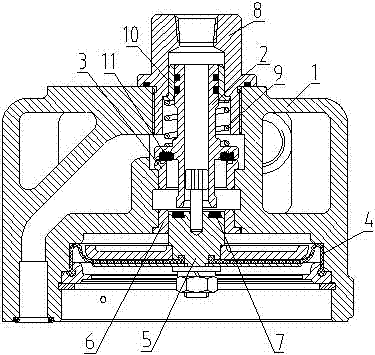
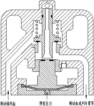
[0017] Such as figure 1 As shown, a relay valve for a rail vehicle braking system includes a valve body 1 and a valve stem 2 disposed in the cavity of the valve body 1. The valve body 1 is provided with three air passages communicating with the inner cavity of the valve body 1. Interface, among them, two gas circuit ports are air intake ports, which are respectively connected to the brake air storage cylinder and pre-control pressure, and one gas circuit port is an air outlet port, which is connected to the brake cylinder or train pipe; the upper part of the valve stem 2 is fitted with elastic The recovery component, the lower end is in contact with the valve port 3, and the valve stem 2 is provided with a central through hole communicating with the outside atmosphere; the valve body 1 is also provided with a pressure adjustment component placed under the val...


PUM


Abstract

The invention relates to a relay valve for a brake system of a railway vehicle. The relay valve comprises a valve body and a valve stem arranged inside a cavity of the valve body; three air channel connectors communicated with the internal cavity of the valve body are arranged on the valve body, two of the air channel connectors are air inlet connectors which are respectively connected with a brake air storage cylinder and controlled pressure, and the other air channel connector is an air outlet connector and is connected with a brake cylinder or a train pipe; an elastic recovery assembly is sleeved on the upper portion of the valve stem, the lower end of the valve stem is in contact connection with a valve port, and a central through hole communicated with the external atmosphere is arranged inside the valve stem; and a pressure regulating assembly placed below the valve stem is further arranged inside the valve body and is used for controlling break-make between the brake cylinder or the train pipe and the atmosphere or the brake air storage cylinder. The relay valve is simple in structure, low in cost and fast in response, and has fast air charging and exhausting properties, outputted pressure can be stably and linearly changed along with change of the controlled pressure, and can be controlled stably, the air flow can be increased or decreased according to the change of the controlled pressure, and functions of air charging, air exhausting or pressure maintaining are realized, so that braking force of the vehicle or a train is controlled.

Description

technical field [0001] The invention relates to a relay valve which is installed in an air brake system and functions by controlling the change of gas pressure in a pipeline, in particular to a relay valve for a rail vehicle brake control system. Background technique [0002] In order to accurately control the compressed air pressure and increase the charging and exhausting rate, the rail vehicle braking system generally uses a relay valve to amplify the air flow and control the pressure value of the compressed air. The relay valve in the traditional railway locomotive braking system accepts the manipulation of the automatic brake valve and acts according to the pressure change of the equalizing air cylinder to directly control the air filling or exhausting of the train pipe. The braking system using this relay valve is Traditional train tube decompression braking method. The relay valve is composed of three parts: double-valve port relay valve, total wind shut-off valve an...

Claims


Application Information

Patent Timeline
Patent Type & Authority Applications(China)
IPC IPC(8): B61H11/10
Inventor 李培署纪铅磊赛华松廖志坚
Owner CRRC QINGDAO SIFANG ROLLING STOCK RES INST
Why Eureka
Try Eureka