Interrupt control circuit, circuit board, electro-optic device, and electronic apparatus

a technology of interrupt control and circuit board, applied in the direction of generating/distributing signals, instruments, sustainable buildings, etc., can solve the problems of low operation speed, increased power consumption of cpu, and difficulty in performing interrupt control to asynchronous type of cpu, so as to achieve the effect of reducing power consumption and speed

Inactive Publication Date: 2010-06-01
SEIKO EPSON CORP
View PDF21 Cites 10 Cited by
  • Summary
  • Abstract
  • Description
  • Claims
  • Application Information

AI Technical Summary

Benefits of technology

[0009]In consideration of the above circumstances, an advantage of the invention is to provide an interrupt control circuit capable of performing interrupt control to the asynchronous CPU, thus achieving a higher speed and lower power consumption. Further, another advantage of the invention is to provide a circuit board, an electro-optic device, and an electronic apparatus each provided with such an interrupt control circuit, and consequently capable of performing interrupt control to the asynchronous CPU, thus achieving a higher speed and lower power consumption.
[0010]According to a first aspect of the invention, there is provided an interrupt control circuit for outputting an interrupt signal for requesting an interrupt processing in accordance with an interrupt cause signal from one of more of external circuit, and an interrupt vector signal for indicating the storing destination of the interrupt processing program corresponding to the interrupt cause signal to an interrupt process executing circuit, and for outputting the interrupt signal in sync with the interrupt acceptance signal input from the interrupt process executing circuit and indicating the state in which an interrupt process can be accepted.
[0011]According to the interrupt control signal having such a feature, since the interrupt signal is output in sync with the interrupt acceptance signal input from the interrupt process executing circuit such as a CPU and indicative of the state in which the interrupt process can be accepted, the common clock required in the related art can be eliminated, and it can correspond to the asynchronous CPU, thus the higher speed and lower power consumption can be realized.
[0012]Further, the interrupt control circuit according to the first aspect of the invention preferably includes an interrupt signal generating circuit for resetting the interrupt signal in sync with setting of the interrupt acceptance signal while setting the interrupt signal in sync with resetting of the interrupt acceptance signal, and an interrupt vector generating circuit for outputting the interrupt vector signal in sync with setting of the interrupt signal.
[0013]In the communication protocol between the asynchronous circuits, it is inhibited that the interrupt control circuit outputs the interrupt signal to the interrupt process executing circuit such as a CPU in a period when the interrupt process executing circuit outputs the interrupt acceptance signal of a set state.
[0014]Therefore, as described above, by resetting the interrupt signal in sync with setting of the interrupt acceptance signal while setting the interrupt signal in sync with resetting of the interrupt acceptance signal, and further outputting the interrupt vector signal in sync with setting of the interrupt signal, the signal communication compliant with the communication protocol between the asynchronous circuits can be performed.

Problems solved by technology

As described above, in the case with the synchronous circuit in the related art, since the monitoring process of the interrupt signal is required, the power consumption of the CPU increases, and further, since all of the operation timings are specified with the clock signal, the operation speed is low.
However, as described above, since the interrupt control circuit in the related art requires the clock signal common to the CPU, it is difficult to perform the interrupt control to an asynchronous type of CPU.
Therefore, the asynchronous CPU can hardly be used, thus it is difficult to realize a high speed and low power consumption interrupt control circuit.
Further, since the interrupt control circuit in the related art is not provided with a function of storing or initializing the state of the interrupt cause signal, such a function needs to be provided to the external circuit side, thus the design work efficiency is deteriorated to incur lengthening of the design period therefor.

Method used


Image

  • Interrupt control circuit, circuit board, electro-optic device, and electronic apparatus
  • Interrupt control circuit, circuit board, electro-optic device, and electronic apparatus
  • Interrupt control circuit, circuit board, electro-optic device, and electronic apparatus

Examples


first embodiment

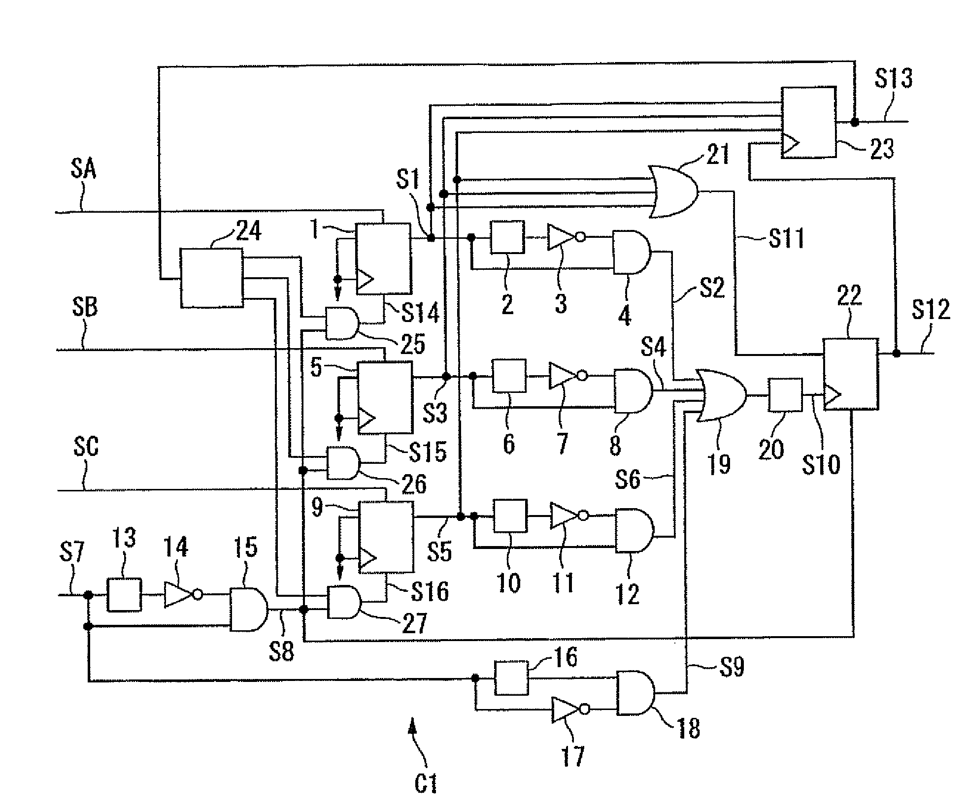
[0049]Firstly, the interrupt control circuit according to a first embodiment of the invention will be explained. FIG. 1 is a block diagram showing a configuration of an interrupt control circuit C1 according to the first embodiment. As shown in FIG. 1, the interrupt control circuit C1 in the first embodiment is composed of a flip-flop circuit 1, a delay circuit 2, an inverter circuit 3, an AND circuit 4, a flip-flop circuit 5, a delay circuit 6, an inverter circuit 7, an AND circuit 8, a flip-flop circuit 9, a delay circuit 10, an inverter 11, an AND circuit 12, a delay circuit 13, an inverter circuit 14, an AND circuit 15, a delay circuit 16, an inverter circuit 17, an AND circuit 18, an OR circuit 19, a delay circuit 20, an OR circuit 21, a flip-flop circuit 22, an interrupt vector generating circuit 23, a decoder circuit 24, an AND circuit 25, an AND circuit 26, and an AND circuit 27.

[0050]The flip-flop circuits 1, 5, and 9 are components corresponding to an interrupt cause stora...

second embodiment

[0081]Then, an interrupt control circuit according to a second embodiment of the invention will be explained. FIG. 3 is a block diagram showing a configuration of an interrupt control circuit C2 according to the second embodiment. It should be noted that in FIG. 3, similar components to those shown in FIG. 1 are denoted with the same reference numerals to omit the explanations therefor, and the points different from FIG. 1 will hereinafter be explained.

[0082]In the second embodiment, there is described a configuration of the interrupt control circuit C2 in the case in which the function of storing and initializing the state of the interrupt cause signal is provided to each of external circuits. In other words, the interrupt control circuit C2 is not provided with the flip-flop circuits 1, 5, and 9, but an external circuit 30 is provided with the flip-flop circuit 1, an external circuit 40 is provided with the flip-flop circuit 5, and an external circuit 50 is provided with the flip-...


PUM


Abstract

An interrupt control circuit includes: a section that generates an interrupt signal for requesting an interrupt in response to occurrence of a plurality of interrupt causes; a section that generates an interrupt vector signal for indicating a storing destination of an interrupt processing program corresponding any of the plurality of interrupt causes; a section that outputs the interrupt signal and the interrupt vector signal to an interrupt process executing circuit; and a section that controls the interrupt signal and an output value of the interrupt vector signal in sync with an interrupt acceptance signal input from the interrupt process executing circuit, the interrupt acceptance signal representing a condition in which an interrupt process is acceptable.

Description

[0001]The entire disclosure of Japanese Patent Application Nos: 2006-352025, filed Dec. 27, 2006 and 2007-327555, filed Dec. 19, 2007 are expressly incorporated by reference herein.BACKGROUND OF THE INVENTION[0002]1. Technical Field[0003]The present invention relates to an interrupt control circuit, a circuit board, an electro-optic device, and an electronic apparatus.[0004]2. Related Art[0005]There is disclosed an example of an interrupt control circuit for performing interrupt control to a central processing unit (CPU) in, for example, Illustrated Introduction to Z80 Microcomputer Application System for Hardware, Second Edition, pp. 186. This interrupt control circuit is composed of an OR circuit for outputting an interrupt signal, which is a logical OR signal of a plurality of interrupt cause signals input from the outside, to the CPU, and an interrupt vector generating circuit for outputting, to the CPU, an interrupt vector signal corresponding to the interrupt cause signal. For...

Claims


Application Information

Patent Timeline
Patent Type & Authority Patents(United States)
IPC IPC(8): G06F13/24G06F13/26G06F13/42
CPCG06F13/24Y02B60/1228Y02D10/00
Inventor NANMOTO, TAKASHI
Owner SEIKO EPSON CORP
Why Eureka
Try Eureka