Cement-based tile-setting spacers and related process

a technology of cement-based tiles and spacers, which is applied in the field of spacers, can solve the problems of reducing affecting the quality of tiles, and affecting the appearance of grout, so as to save time and money, reduce the risk of damage to tiles, and eliminate the effect of damag

Inactive Publication Date: 2007-01-18
FRANK KEITH +1
View PDF21 Cites 30 Cited by
  • Summary
  • Abstract
  • Description
  • Claims
  • Application Information

AI Technical Summary

Benefits of technology

[0006] The present invention resides in a spacer and a process for making a spacer. The present invention provides spacers in a wide range of sizes and configurations and saves time and money by eliminating the tedious task of having to manually remove spacers prior to grouting as spacers embodying the present invention can be left permanently imbedded in the bonding materials (e.g., thinset, grout or the like) used to install tiles. This reduces and / or eliminates the risk of damaging tiles with a screwdriver or other tool that can occur when someone setting tiles attempts to extract spacers that need to be removed.
[0010] Preferably, the at least two spacer legs comprise, at least in part, a variety of shapes including, without limitation, a linear shape, a V-shape, a Y shape, a T shape, a U shape, an L shape, an I shape, an X shape or the like. The spacer includes a line of weakness between the common junction and at least one of the legs for aiding in removal of the at least one leg from the spacer.

Problems solved by technology

However, laying out individual ceramic tiles in the positions that make up a chosen tile pattern is a costly process in terms of labor, expense and time.
However, removal of the spacers is labor intensive, slow and can result in damage to the tiles.
Attempts to simply leave the spacers in position and grout the spacers over have had poor results, causing the grout to appear discolored, lumpy, and even to crack and break due to poor bonding between the spacers and the grout.
Thus, the spacers must be removed prior to grouting and this removal makes the process of installing tiles costly, in terms of labor, time and expense.

Method used


Image

  • Cement-based tile-setting spacers and related process
  • Cement-based tile-setting spacers and related process
  • Cement-based tile-setting spacers and related process

Examples


Embodiment Construction

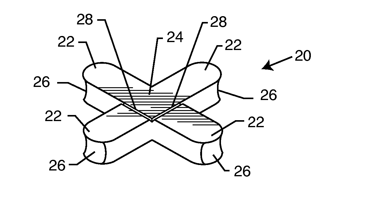
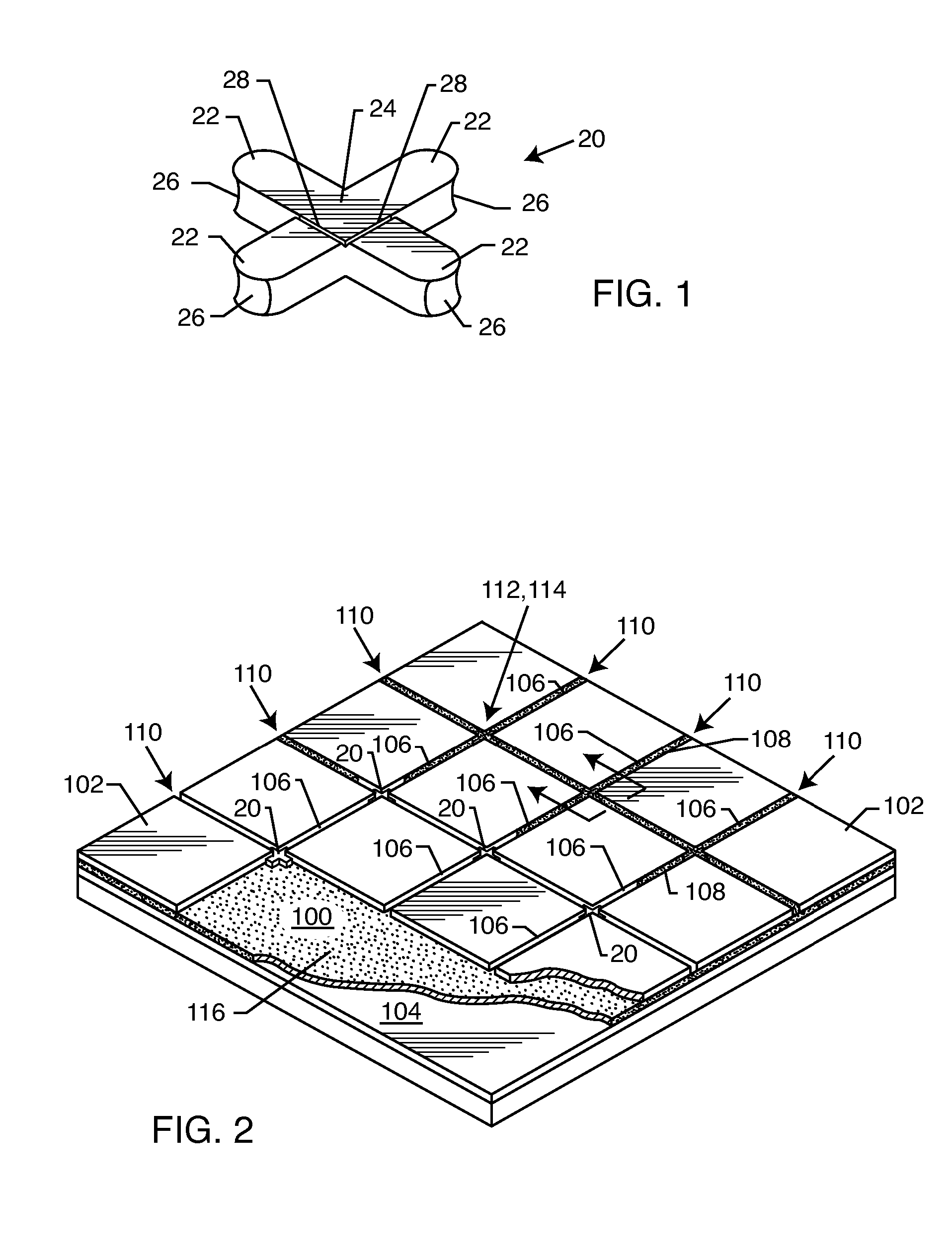
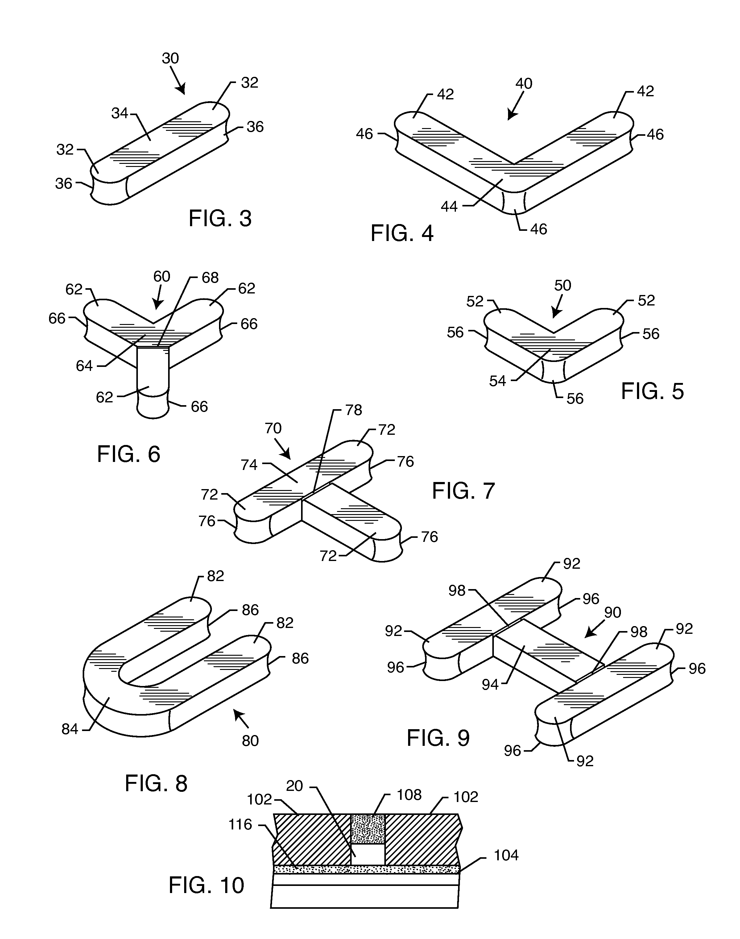
[0029] As seen in FIGS. 1-10, the present invention resides in a tile-setting spacer 20, 30, 40, 50, 60, 70, 80, 90. An X-shape spacer 20 includes four limbs or legs 22 extending radially outward from a common junction 24 to form the X-shape or cross-shape (approximate size being one inch by one inch in length and width, with a thickness of three sixteenths inch to one half inch). There is a slight, concave recess or cutout 26 at an end of each leg 12 distal from the common junction 24. However, in addition to the X-shaped spacer 20, a tile spacer can also come in a variety of other shapes including, without limitation, a linear shape 30 (FIG. 3), an L-shape 40 (FIG. 4), a V-shape 50 (FIG. 5), a Y-shape 60 (FIG. 6), a T-shape 70 (FIG. 7), a U-shape 80 (FIG. 8), an I-shape 90 (FIG. 9) or the like. Each spacer 30, 40, 50, 60, 70, 80, 90 includes a number of radial limbs or legs 32, 42, 52, 62, 72, 82, 92 extending radially outwardly from a common junction 34, 44, 54, 64, 74, 84, 94 to...


PUM


Abstract

A spacer providing a substantially uniform space between adjacent tiles includes spacer legs extending radially from a common junction. The spacer legs, made from a porous material, are permanently adherable to a tile bonding material utilized to adhere the tiles to an underlying surface, and / or a grout material filling a gap between tiles. A process for making a tile spacer includes providing thinset material to which a liquid latex admix material is added. The materials are distributed evenly to a consistency of a damp fluffy sand-like mixture which is then placed into a mold of a desired shape and packed into the mold to bond the materials while still damp to form the tile spacer. The spacer is extracted from the mold and placed on a flat rigid sheet. The spacer is moist cured and dried at room temperature environment with 40-99% humidity.

Description

BACKGROUND OF THE INVENTION [0001] The present invention generally relates to spacers for maintaining uniform distances between tiles and the like. More particularly, the present invention relates to cementitious based tile setting spacers. [0002] Ceramic tile is ubiquitous as a floor and / or wall covering in office, retail, residential and industrial spaces. However, laying out individual ceramic tiles in the positions that make up a chosen tile pattern is a costly process in terms of labor, expense and time. [0003] Conventionally, a tile is set in a particular position in the tile pattern by applying a coat of thinset or the like to a surface the tile is going to be placed on. The individual tiles of the pattern are placed, side-by-side, in contact with the thinset. Typically, adjacent tiles are spaced apart from one another and, once the thinset under the tiles has cured, this space between the tiles is filled with grout to form sealed connections between the tiles. The grout adds...

Claims


Application Information

Patent Timeline
Patent Type & Authority Applications(United States)
IPC IPC(8): G01D21/00
CPCE04F21/0092
Inventor FRANK, KEITHGERLING, SCOTT
Owner FRANK KEITH
Why Eureka
Try Eureka