
Needle assembly with diagnostic analysis provisions

a technology of needle assembly and diagnostic analysis, which is applied in the direction of diagnostic recording/measuring, catheters, applications, etc., can solve the problems of increasing the risk of the pen itself becoming contaminated, putting the clinician and other patients at risk of making contact with trace amounts of blood, and reducing the risk of fluid spillage, reducing the possibility of inadvertent needle stick use

Active Publication Date: 2018-07-24
SMITHS MEDICAL ASD INC
View PDF55 Cites 7 Cited by
  • Summary
  • Abstract
  • Description
  • Claims
  • Application Information

AI Technical Summary

Benefits of technology

[0014]Embodiments of the present disclosure meet the need for providing a better way of accessing and testing the fluid trapped in the flashback chamber of a needle assembly in a manner that reduces or eliminates the risk of the fluid spilling, while reducing the possibility of an inadvertent needle stick.
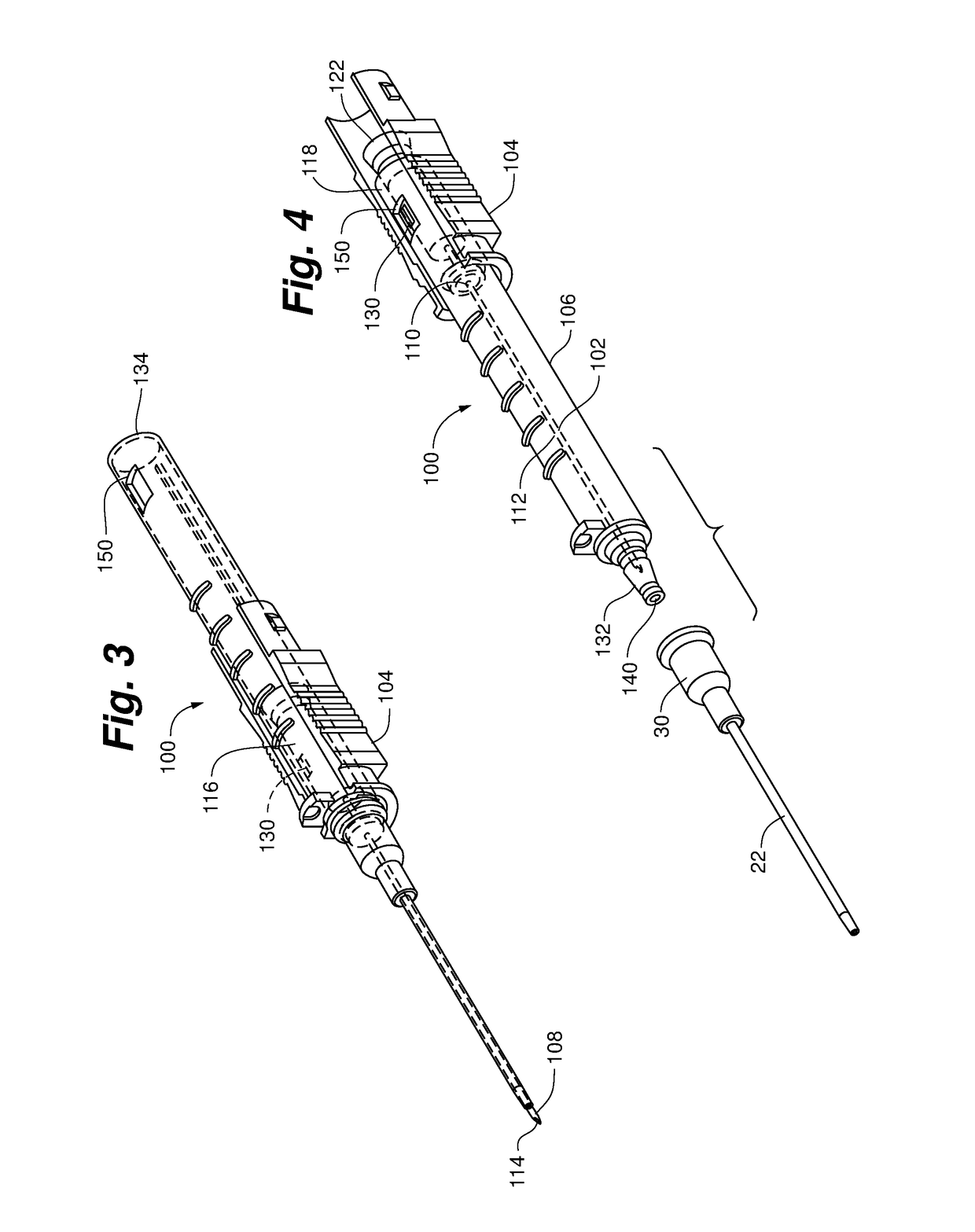
[0015]One embodiment of the present disclosure provides a safety needle assembly that enables access to fluid trapped in the flashback chamber after the insertion needle has been safely housed, thereby reducing the risk of an inadvertent needle stick. In addition, the risk of the fluid spilling is greatly reduced, as the fluid is tested by inserting a test strip directly into the flashback chamber via a diagnostic sampling port. This embodiment includes an insertion needle, a needle hub and a needle housing. The insertion needle has a sharpened distal tip, a proximal end and a shaft defining a lumen extending therebetween. The needle hub is operably coupled to the proximal end of the insertion needle. The needle hub includes a flash chamber comprising a wall defining a cavity in fluid communication with the lumen of the insertion needle and sealed at one end by a gas permeable flash plug. The cavity defining wall further includes structure defining a diagnostic sampling port configured to enable selective access to the cavity. The needle housing is slideably coupled to the needle hub, and is moveable between a first position wherein the sharpened distal tip extends from the needle housing, and a second position wherein the sharpened distal tip is housed within the needle housing. The needle housing includes structure defining an access port that aligns with the diagnostic sampling port when the needle housing is in one of the first position and the second position.

Problems solved by technology

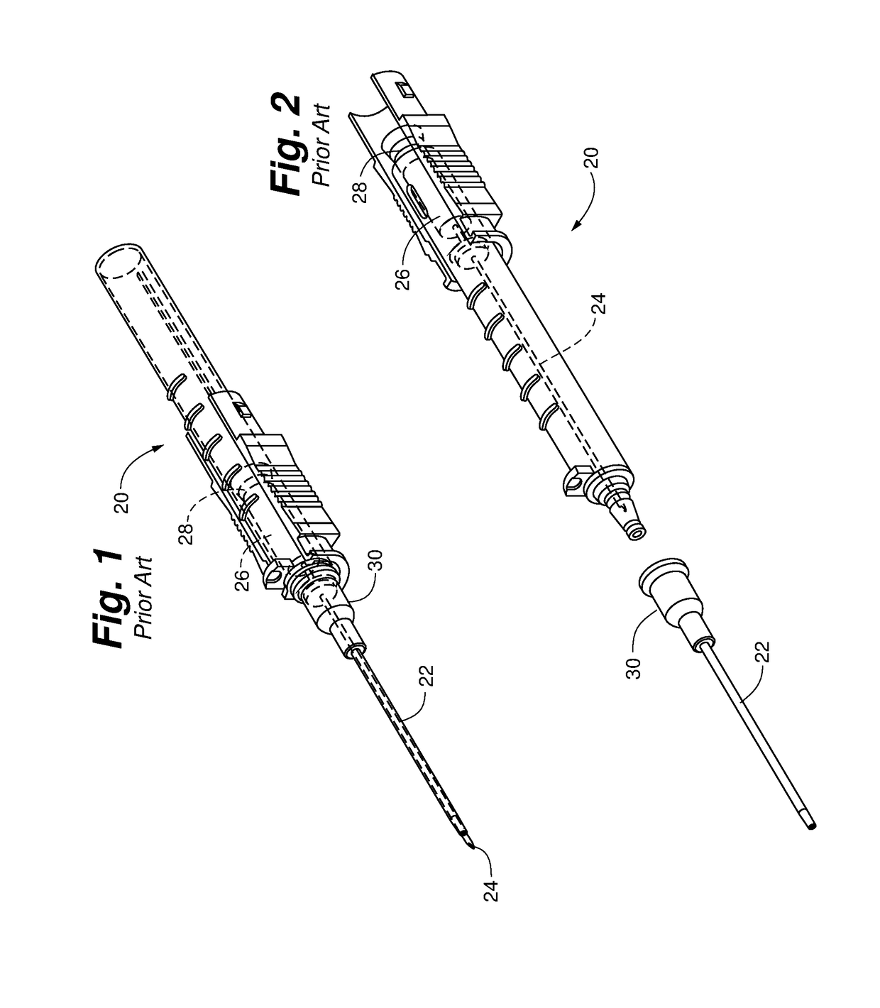
The use of an external device such as a pen can be undesirable for several reasons.
In particular, it is cumbersome in that it requires that the clinician find a pen or similar object, and use both hands to access the blood within the flash chamber 26.
It increases the risk that the pen or other object, which may not be sterile, if improperly handled, will contaminate the blood and cause inaccuracies in the following tests.
And, if improperly handled, it increases the risk that the pen itself will become contaminated from the blood within flash chamber 26, thereby putting the clinician and other patients at risk of making contact with trace amounts of the blood.

Method used


Image

  • Needle assembly with diagnostic analysis provisions
  • Needle assembly with diagnostic analysis provisions
  • Needle assembly with diagnostic analysis provisions

Examples


first embodiment

A. First Embodiment

[0051]Referring to FIGS. 3-8, a safety needle assembly 100 according to a first embodiment of the disclosure is depicted. Safety needle assembly 100 can include an insertion needle 102, a needle hub 104, and a needle housing 106. Insertion needle 102 can have a sharpened distal tip 108, a proximal end 110 and a shaft 112 defining a lumen 114 extending therebetween.

[0052]Needle hub 104 can be operably coupled to the proximal end 110 of the insertion needle 102. As depicted in FIGS. 5 and 6A-C, the needle hub 104 can include a flash chamber 116 comprising a wall 118 defining a cavity 120. In one version, the cavity defining wall 118 can be constructed of a transparent or translucent material to enable a clinician to visually see when fluid enters the cavity 120.

[0053]The cavity 120 can be in fluid communication with the lumen 114 of the insertion needle 102. For example, in one version, the distal end 124 of the flash chamber 116 can include an aperture 126 sized to...

second embodiment

B. Second Embodiment

[0061]Referring to FIGS. 9 and 10, a safety needle assembly 200 according to a second embodiment of the disclosure is depicted. In this embodiment, the access port 250 can be positioned in proximity to the distal end 232 of needle housing 206 to align with the diagnostic sampling port 230 when the needle housing 206 is in the first position. Positioning access port 250 in this location enables diagnostic sampling port 230 to be housed within the needle housing 206 in the second position; thereby reducing the likelihood that fluid will spill from the cavity 220 of flash chamber 216 should diagnostic sampling port 230 leak or fail.

fourth embodiments

C. Third and Fourth Embodiments

[0062]Referring to FIGS. 11 and 12, safety needle assemblies 300 and 400 according to a third and fourth embodiment of the disclosure are depicted. Safety needle assemblies 300 and 400 can include removable sample vials 352, 452. In one version, the sample vial 352, 452 can be comprised of a tubular member 354, 454 that selectively couples to access port 350, 450. Tubular member 354, 454 can include a sample vial flash plug 356 to enable air to escape as sample vial 352, 452 fills with fluid. In some versions, the sample vial flash plug 356 can be used in place of or as a replacement for a flash plug positioned within the flash chamber.

[0063]In some versions, safety needle assemblies 300 and 400 can include at least one of a protective needle housing 380, 480, a self-contained antiseptic swab, and a tourniquet for treatment and / or preparation of a biological site of a patient. Various catheter insertion devices having protective needle housings, a self...


PUM


Abstract

A needle assembly. The needle assembly enabling the analysis of fluid trapped in a flashback chamber after an insertion needle has been inserted into a patient's vein.

Description

RELATED APPLICATIONS[0001]The present application claims the benefit of U.S. Provisional Application Nos. 62 / 109,673; 62 / 109,710; 62 / 109,715; 62 / 109,722; 62 / 109,735; 62 / 109,742; 62 / 109,745; 62 / 109,750; 62 / 109,755; 62 / 109,759; 62 / 109,766, all of which were filed Jan. 30, 2015 and are hereby incorporated herein by reference.TECHNICAL FIELD[0002]The present disclosure relates generally to needle assemblies, and more particularly to a needle assembly having diagnostic sampling provisions to enable the testing and analysis of fluid captured by the needle assembly after needle insertion.BACKGROUND[0003]Intravenous (IV) therapy is a versatile technique used for the administration of medical fluids to and withdrawal of bodily fluids from patients. IV therapy has been used for various purposes such as the maintenance of fluid and electrolyte balance, the transfusion of blood, the administration of nutritional supplements, chemotherapy, and the administration of drugs and medications. Fluids ...

Claims


Application Information

Patent Timeline
Patent Type & Authority Patents(United States)
IPC IPC(8): A61B5/15A61B5/153A61M25/00A61M5/32A61M5/42A61M39/22A61M21/02A61M25/06A61B17/132A61M21/00
CPCA61B5/150824A61B5/1535A61B5/150221A61B5/150259A61B5/150732A61M5/3202A61M5/422A61M21/02A61M25/0097A61M25/0631A61B5/15003A61M2205/0205A61B17/1325A61M25/0693A61M39/22A61M2021/0016A61B5/145A61B5/14539A61B5/1477A61B5/150992A61B5/157A61B2010/0006A61B5/150213A61B5/150358A61B5/150389A61B5/150503A61B5/150641
Inventor GORAL, DAVIDCHHEDA, HARSHBREINDEL, JAYAKCAY, GURSELMUSKATELLO, JAMESJUSTMANN, DAVID
Owner SMITHS MEDICAL ASD INC
Learn More