Spindle clamp

a technology of spindle clamping and spindle locking mechanism, which is applied in the direction of measuring devices, structural/machine measurement, instruments, etc., to achieve the effect of improving the quality of balancing, increasing the resistance of the spindle locking mechanism to the machining force, and extreme rigid characteristics

Active Publication Date: 2012-11-08
FRANZ HAIMER MASCHINENBAU KG
View PDF4 Cites 8 Cited by
  • Summary
  • Abstract
  • Description
  • Claims
  • Application Information

AI Technical Summary

Benefits of technology

[0014]According to a modification of the invention, there are at least two clamping strips whose clamping surfaces are arranged in different planes, preferably extending essentially perpendicularly or obliquely to each other. Generally speaking, there are thus two separate clamping systems, the first of which immobilizes the spindle unit against the action of forces from a first direction and the second immobilizes the spindle unit against the action of forces from a second direction, which differs from the first direction. Preferably, the first direction corresponds to a direction parallel to the rotation axis of the spindle and the second direction corresponds to a direction perpendicular thereto, preferably with the two directions simultaneously also being oriented perpendicular to the measurement direction M of the sensor or sensors. Such an embodiment makes it possible to immobilize the spindle unit in a way that is altogether rigid by clamping the clamping strips in place, even though each of the clamping strips is flexible or elastically resilient in one direction—in this way, the clamping strips reinforce and complement each other in their function. This gives the spindle locking mechanism extremely rigid characteristics and enables a high-precision removal of material from the test piece or tool holder, which improves the quality of its balancing.
[0015]Preferably, at least two clamping strips are provided, which are arranged parallel to and spaced apart from each other. Such an arrangement increases the resistance of the spindle locking mechanism to the machining forces produced in the course of the removal of material from the test piece, which have a tendency to tilt the spindle unit.
[0016]It is advantageous if the clamping jaws each include a pivoting strip, which has an elastically deformable holding slat around which the pivoting strip is pivoted against the clamping strip in the course of the actuation of the clamping jaw. It is thus possible to eliminate a hinge with elements that move in sliding fashion relative to each other so that the pivoting strip articulates. This improves measurement precision and reliability since it is never possible to completely rule out the fact that a hinge—at least over the long term—will end up having too much play and will thus begin to “rattle” to a minimal degree, which impairs the accurate detection of very small imbalance-induced movements.
[0017]In a preferred modification of the invention, at least two clamping jaws are actuated by a shared actuator. Such an embodiment is useful not only because it reduces the number of moving parts, but also because it reduces or eliminates the risk that as the spindle unit is being clamped into position, this very process causes forces to be exerted on the spindle unit so that different actuators generate different forces depending on tolerances.

Problems solved by technology

Therefore the spindle unit is not clamped in a fashion similar to an external brake drum, for example, i.e. is not clamped with the aid of at least two clamping jaws that engage opposing circumference regions of the spindle unit on both sides of the spindle rotation axis, thus inevitably forcing the spindle arrangement to change position as soon as it is not situated (due to inevitable, more or less random thermal expansions) absolutely symmetrically between the clamping jaws that are to move toward each other with the clamping action.

Method used


Image

  • Spindle clamp
  • Spindle clamp
  • Spindle clamp

Examples


Embodiment Construction

[0031]First, a brief general description should be given of the function of the exemplary embodiment presented here for the purpose of further illustrating the invention.

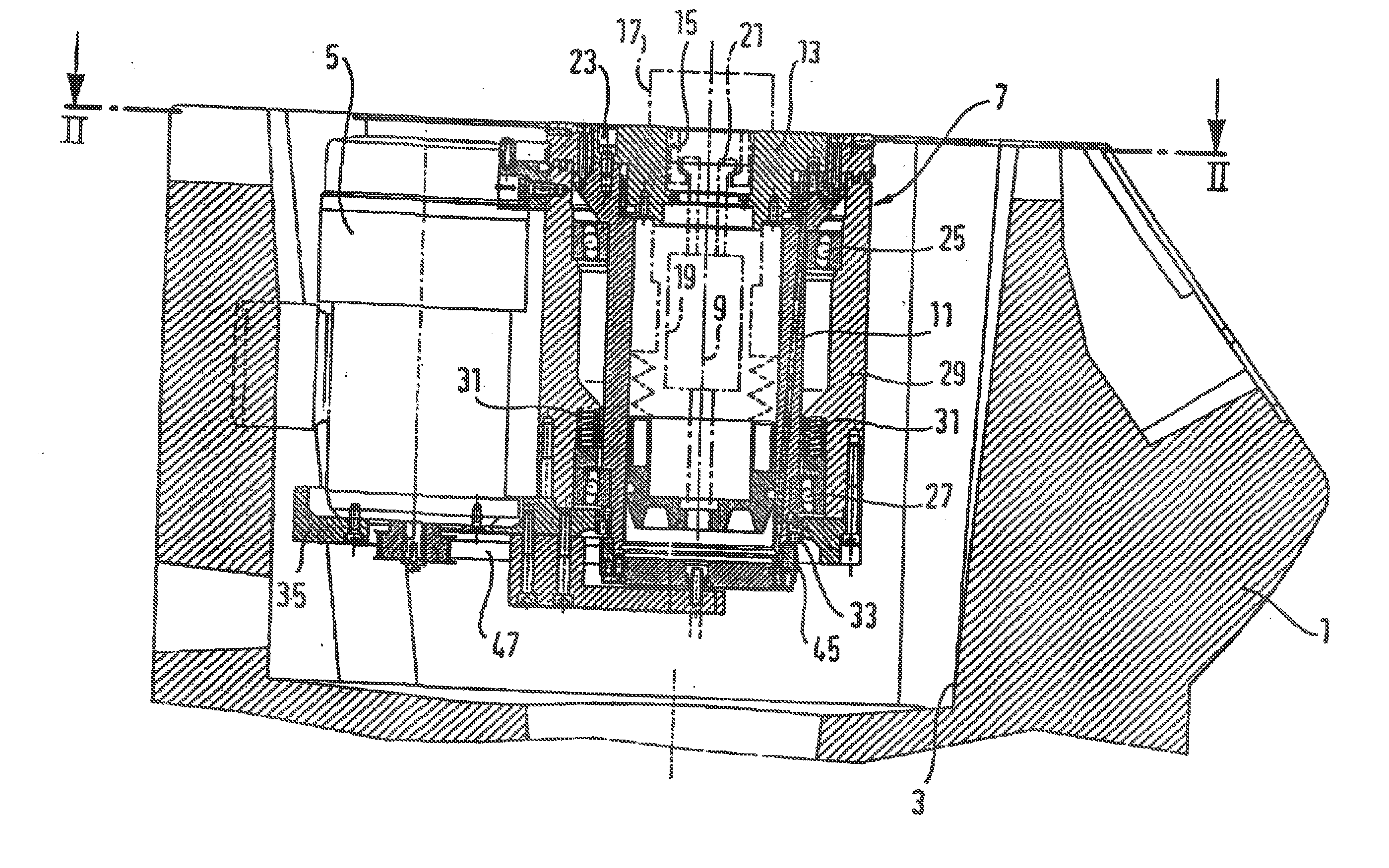
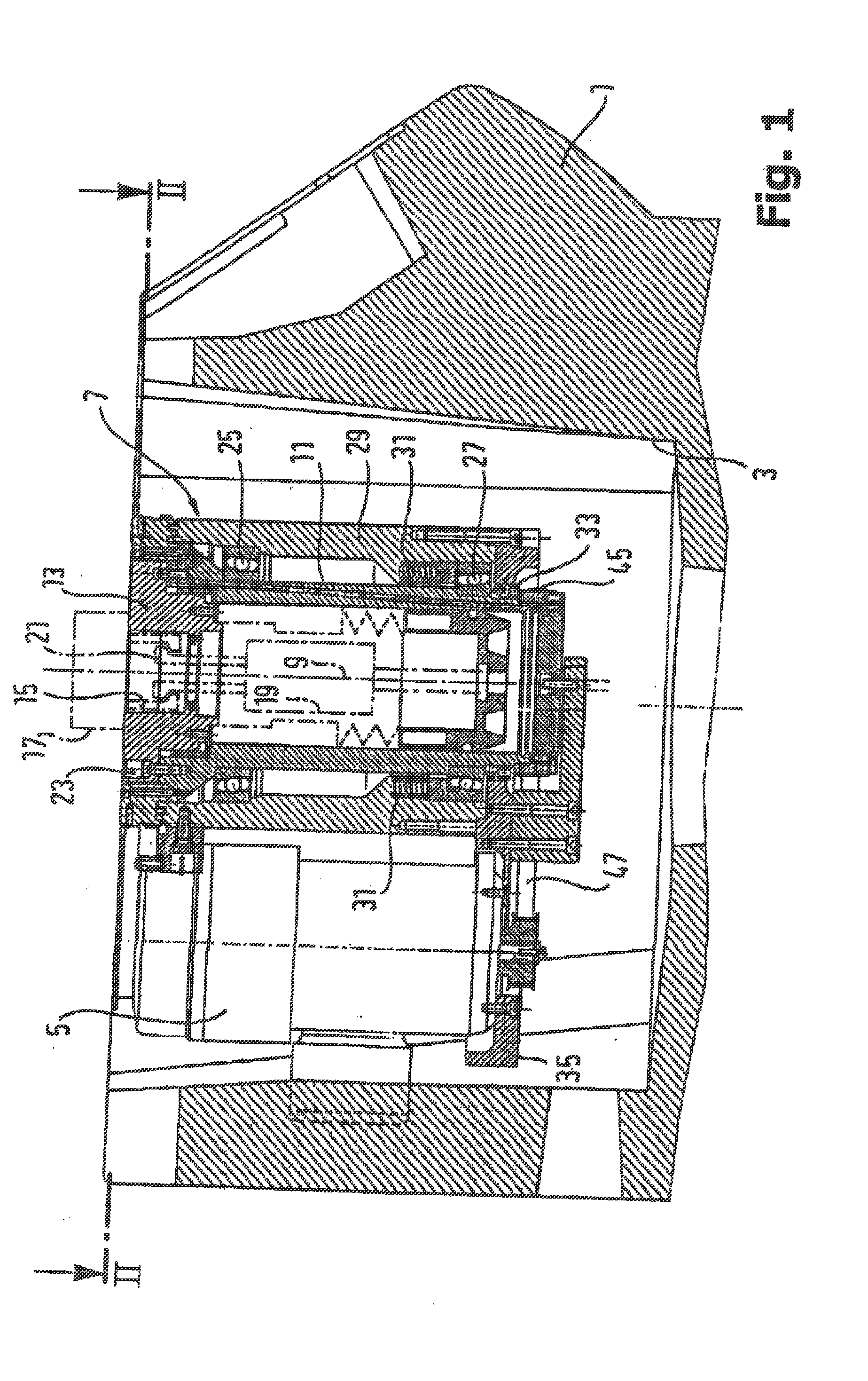
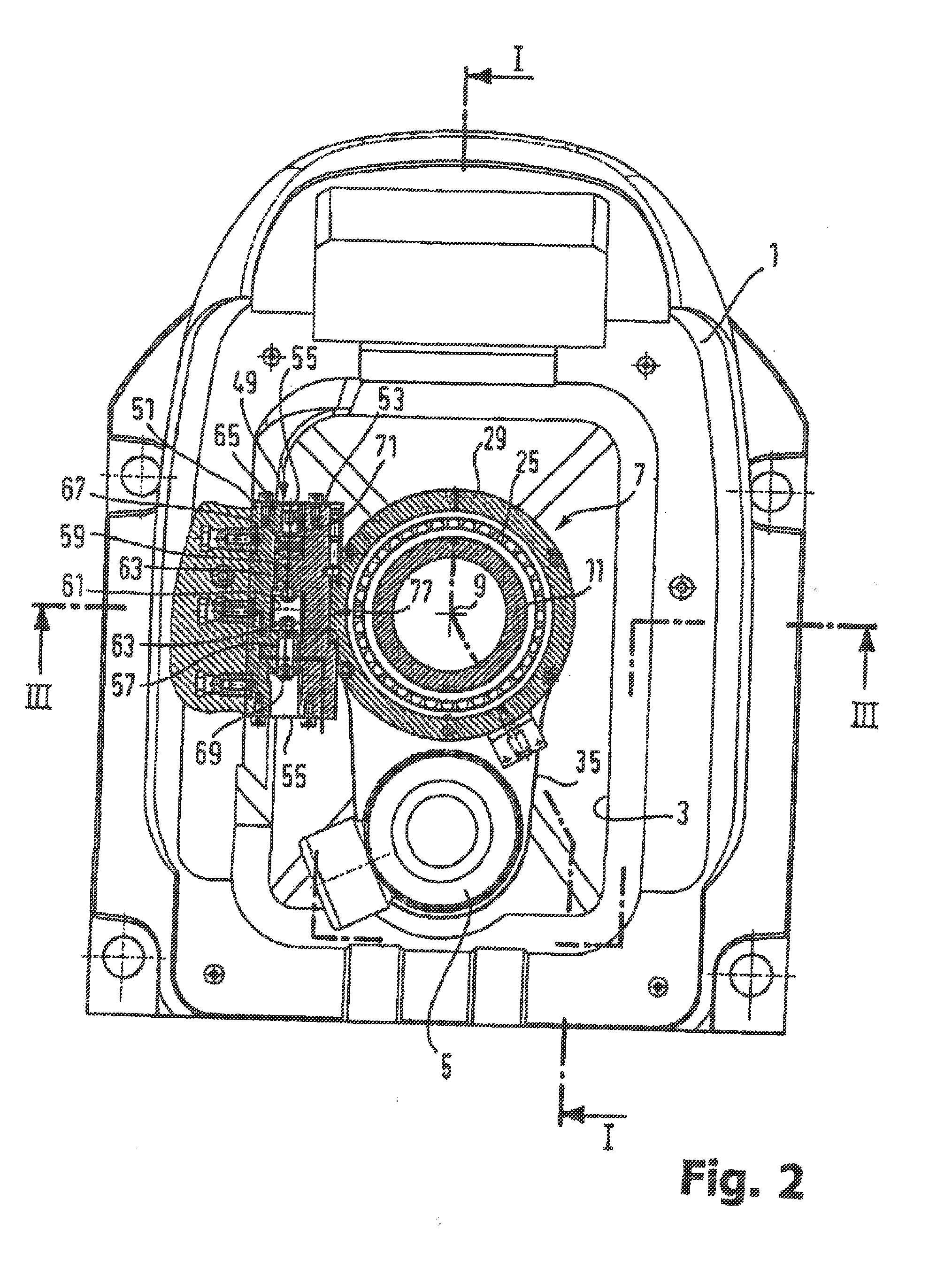
[0032]The balancing machine shown in an overview in the FIGS. 1 and 2 has a housing 1 serving as the base of the machine. In a chamber 3 that is accessible from above, the housing accommodates a spindle unit 7 that is driven by an electric motor 5. The spindle unit 7 has a rotating spindle 11 whose rotation axis 9 is preferably oriented vertically.

[0033]At its upper end, the spindle has a coupling adapter 13, which can be replaced during normal operation and is equipped with a receiving opening centered on the rotation axis 9. This receiving opening is used for connecting a standardized test piece that is to be balanced, which in this case is represented by the tool holder 17. The test piece can be a tool holder, e.g. embodied in the form of a conventional taper or hollow shank taper tool holder (HSK tool holder), o...


PUM

PropertyMeasurementUnit
widthaaaaaaaaaa
widthaaaaaaaaaa
speedaaaaaaaaaa

Abstract

The invention relates to a balancing device, having a measuring system for determining the rotational unbalance of a test object, comprising a spindle unit with a spindle, which is intended to hold the test object and rotate it at a test rotational speed, and a spindle mounting, by which the spindle unit is movably anchored on the machine base, such that the spindle unit can oscillate in a predetermined measuring direction as a result of the unbalance forces occurring during the measurement operation, and at least one sensor, which upon rotation of the spindle detects at least one unbalance characteristic variable occurring in the measuring direction, and a material removal system for balancing the test object by material removal in a predetermined site. The measuring system and the material removal system are designed such that material can be removed when the test object is held in the spindle.

Description

FIELD OF THE INVENTION[0001]The invention relates to a balancing machine, also referred to as a balancing device, for determining and eliminating the rotational imbalance of a test piece (in particular in the form of a tool holder).BACKGROUND OF THE INVENTION[0002]Devices that enable high-precision determination of the amount and location of the imbalance of a tool holder are known, for example, from the German patent application DE 102 33 917 A1.[0003]Once the amount and location of the imbalance have been determined, it is also known to remove some material from a suitable location on the tool holder in order to thus permanently balance the tool holder.[0004]As a rule, the tool holder is unclamped from the balancing machine for this purpose and the necessary amount of material is removed from the predetermined location. The tool holder is then clamped back into the balancing machine to perform a test measurement. The unclamping and reclamping is time-consuming and may compromise m...

Claims


Application Information

Patent Timeline
Patent Type & Authority Applications(United States)
IPC IPC(8): G01M1/02
CPCG01M1/02G01M1/34G01M1/04Y10T408/03
Inventor HAIMER, FRANZ
Owner FRANZ HAIMER MASCHINENBAU KG
Why Eureka
Try Eureka