
Method for balancing component

A technology for balancing components and components, applied in the field of motor components, motors, devices, and rotors of motors, can solve problems such as high requirements, achieve high stability and improve the effect of balancing quality

Active Publication Date: 2015-08-12
SIEMENS AG
View PDF9 Cites 0 Cited by
  • Summary
  • Abstract
  • Description
  • Claims
  • Application Information

AI Technical Summary

Problems solved by technology

However, this method places high demands on the personnel performing the balancing

Method used


Image

  • Method for balancing component
  • Method for balancing component
  • Method for balancing component

Examples


Embodiment Construction

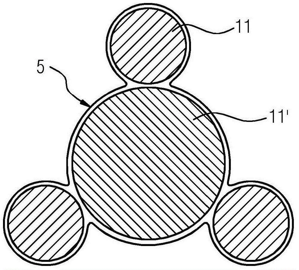
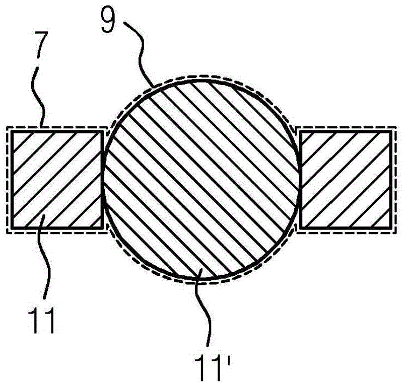
[0023] figure 1 A top sectional view of the assembly 1 is shown. In assembly 1 there is a cross-section of the composite lamination 3 of the rotor of the electric machine. The combined laminations have, for example, gaps 4 for weight reduction, and openings 5, 7, 9. Such as figure 2 As shown again in , the opening 5 consists of circular openings 7 , 9 . The circular openings 7 , 9 serve to accommodate corresponding cylindrically shaped pins 11 , 11 ′. The shown arrangement proves to be space-saving, in which the opening 5 for receiving the cylindrically shaped pins 11 , 11 ′ is located between the two gaps 4 . The arrangement shown thus facilitates reducing the weight, the inertia factor and the space requirement of the composite lamination 3 . In order to balance the assembly, the assembly is put into rotation and the centrifugal moment generated at this time is measured. Next, the weight of the pin 11 , 11 ′ for each opening 7 , 9 is calculated and the corresponding p...


PUM


Abstract

The method involves arranging cylinder or angular-shaped pins into prefabricated apertures (5, 7, 9) in a component (1). The component is balanced into the respective apertures by using the cylinder or angular-shaped pins with different sizes, where the cylinder or angular-shaped pins are manufactured from aluminum, steel, zinc, tungsten, lead, resin or plastic. The cylinder or angular-shaped pins are arranged together to form cross section areas with different sizes. The cylinder or angular-shaped pins are inserted in the apertures after determination of imbalance of the component. Independent claims are also included for the following: (1) a component (2) an electrical rotating machine (3) a device for heaving a component.

Description

technical field [0001] The invention relates to a method for balancing a component, in particular a rotor of an electric machine. Furthermore, the invention relates to an electric machine assembly, which is balanced by such a method, and an electric machine, which has such an assembly. The invention also relates to a device with which components are balanced by means of the method according to the invention. Background technique [0002] Components that rotate during their use often require balance. In balancing, mass compensation occurs axially and radially with respect to the axis of rotation so that the axis of rotation of the assembly coincides with the main axis of inertia of the assembly. If the axis of rotation does not coincide with the main axis of inertia, a centrifugal moment occurs when the component rotates, which in particular loads the suspension of the rotating component. This condition is often referred to as the effect of component imbalance. A centrifu...

Claims


Application Information

Patent Timeline
Patent Type & Authority Applications(China)
IPC IPC(8): F16F15/32H02K7/04H02K15/16
CPCF16F15/32H02K7/04H02K15/165G01M1/32
Inventor 延斯·弗里德里克马丁·库恩
Owner SIEMENS AG
Learn More