Apparatus and method for removing contaminants from a gas stream

Inactive Publication Date: 2007-01-18
TANDON HANS P +1
View PDF15 Cites 13 Cited by
  • Summary
  • Abstract
  • Description
  • Claims
  • Application Information

AI Technical Summary

Benefits of technology

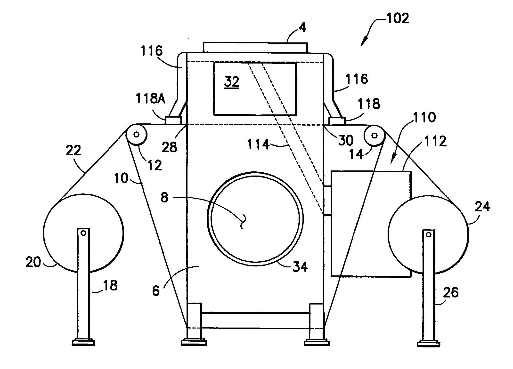
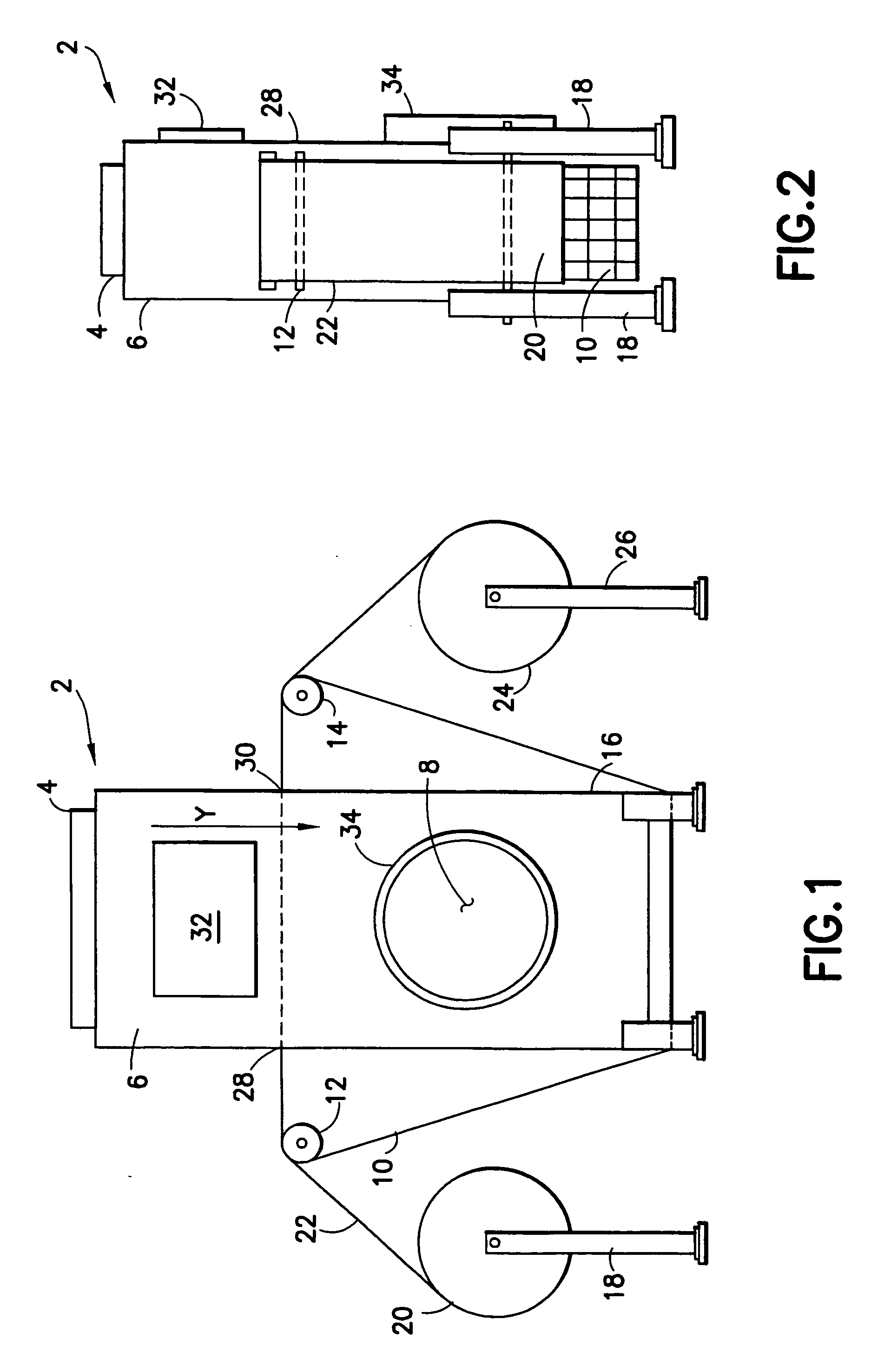
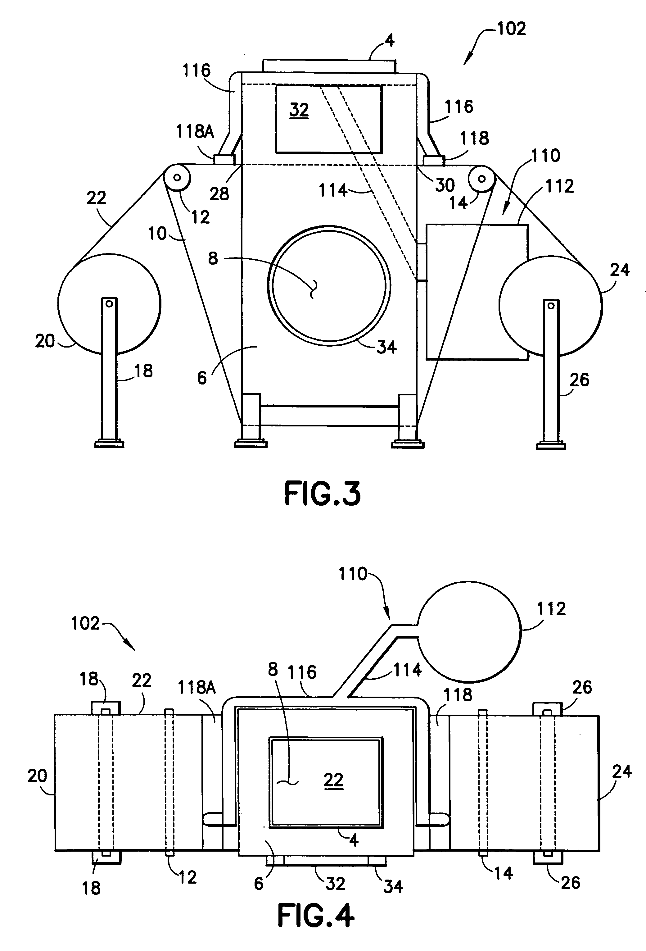
[0010] The present invention further includes a method of removing these materials from gas streams including steps of providing a gas stream containing the materials for removal in the above-described system; selecting a filter media for filtering the gas, selecting a gas velocity, and selecting a gas temperature that together provide a desired control effect on the gas stream to remove the materials therefrom; and passing the gas stream through the selected filter media at the selected velocity to remove the materials from the gas stream.
[0011] In another embodiment o

Problems solved by technology

Such contaminants can cause a range of problems, including undesirable air emissions to the atmosphere that exceed regulatory limits and can cause adverse health effects; air emissions that cause safety, housekeeping, or nuisance problems; undesirable contamination of indoor air environments; problematic contamination in waste gas, off-gas, or other gas streams to be used as fuels; contamination of process air streams causing problems in a product

Method used


Image

  • Apparatus and method for removing contaminants from a gas stream
  • Apparatus and method for removing contaminants from a gas stream
  • Apparatus and method for removing contaminants from a gas stream

Examples


example 1

Mercury Control

[0041] Wastewater treatment gas exhaust from a sludge incinerator was treated according to the present invention. Fine particulate and mercury were removed with a fine particulate filter media (as described above) followed by a section of activated carbon filter media. Mercury was removed at approximately 50% efficiency in a single pass across the filter in both tests, which used the equivalent of ⅜″ thick activated carbon-containing media described previously, as shown in Table 2. EPA Test Method 29, modified, was used for mercury determination. Multiple units in series, multiple passes through the same media and / or use of impregnated activated carbon, can be used to increase the removal efficiency from 50% to 95%+.

TABLE 2Efficiency of Mercury RemovalRun 1Run 2Filter media—Stage 1A8-AA8-AFilter media—Stage 2AC-M (3 / 16″× 2)AC-J (3 / 8″)Control Efficiency (%)55.3%47.3%

example 2

Ultra-Fine Particulate Control, Full Scale

[0042] Smoke from a waste incinerator having a particle size distribution as shown in Table 3 was treated according to the present invention by a full-scale version of the invention. Table 3 shows data on the particle size distribution of smoke filtered as in this example. The system demonstrated an average of 94% removal of the fine smoke particulate, including removing a majority of the ultra-fine particulate (i.e., under 0.55 micron size), over three one-hour tests.

TABLE 3Particle Size Distribution for Full-Scale Particulate TestFlowParticleRateTare WtFinal WtNet Wt% inCumulativeSize(ACFM)Stage(g)(g)(mg)Size Range(microns)0.5600.149730.151431.701.7398.34.00.5610.143450.145682.232.2696.09.00.5620.151410.153181.771.8094.26.00.5630.143060.144641.581.6092.64.10.5640.150180.152442.262.2990.32.60.5650.140530.1614120.8821.2069.11.30.5660.15110.1757624.6625.0444.10.820.5670.139960.1555515.5915.8328.20.550.56Backup0.165270.1930827.8128.24—Filte...

example 3

Ultra-Fine Particulate Control, Pilot Scale

[0043] A standardized particle sample having a known particle size distribution from 0.1-10 microns was treated in a pilot scale version of the present invention in air at 100 fpm using an electrically charged synthetic fiber filter. The ability of the electrically charged filter media at this gas velocity to remove fine particles is shown in FIG. 5 where the filtration efficiency was over 98% for the ultra-fine particle sizes in the sample.


PUM

PropertyMeasurementUnit
Temperatureaaaaaaaaaa
Thicknessaaaaaaaaaa
Thicknessaaaaaaaaaa

Abstract

A pollution control system including a filtering unit for removing contaminants present in air streams or other gas streams including mercury, ultra-fine particulates, siloxanes, heavy metals, ultra-fine aerosols and mists (e.g., oil mists), condensed hydrocarbons, volatile organic compounds (VOCs), odors, radioactive emissions, gas-phase contaminants and microorganisms which includes a fixed filter section or belt style movable filter which can be automatically replaced with a new filter section.

Description

CROSS REFERENCE TO RELATED APPLICATIONS [0001] This application claims the benefit of U.S. Provisional Application No. 60 / 696,715, entitled “Apparatus and Method for Removing Contaminants from a Gas Stream”, filed Jul. 5, 2005, and herein incorporated by reference in its entirety.BACKGROUND OF THE INVENTION [0002] 1. Field of the Invention [0003] The present invention relates to methods of removing materials from a gas stream, more particularly to removing contaminants and / or recovering products from a gas stream via filtration and / or adsorption. [0004] 2. Description of Related Art [0005] Contaminants present in air streams or other gas streams may include mercury, ultra-fine particulates, siloxanes, heavy metals, aerosols and mists (e.g., oil mists), condensed hydrocarbons, volatile organic compounds (VOCs), explosive dusts, odors, radioactive emissions, gas-phase contaminants, bacteria and viruses. Such contaminants can cause a range of problems, including undesirable air emissio...

Claims


Application Information

Patent Timeline
IPC IPC(8): B01D46/00
CPCB01D46/0036B01D46/18B01D46/0068B01D46/0065B01D46/681B01D46/71B01D46/682
Inventor TANDON, HANS P.TANDON, CHRISTINE ILLIG
Owner TANDON HANS P
Why Eureka
Try Eureka