Charging device, especially charging stock preheater

a charging device and charging stock technology, applied in the direction of preheating charges, blast furnace components, containers, etc., can solve the problems of affecting the transport process, affecting the operation of the preheater, and easily becoming jammed by scraps of smaller pieces, etc., to achieve quick connection to the vessel, quick separation from the vessel, and robust and reliable design

Inactive Publication Date: 2007-01-18
FUCHS TECH
View PDF22 Cites 38 Cited by
  • Summary
  • Abstract
  • Description
  • Claims
  • Application Information

AI Technical Summary

Benefits of technology

[0005] It is an object of the invention to design a charging device of the type indicated above in such a way that charging stock of widely differing sizes, such as heavy and light scrap, can be transported to the discharge opening and discharged from it by the pusher without the occurrence of the previously mentioned problems, that is, without malfunctions or blockages. In particular, this should also be ensured in the case of a charging device designed as a charging stock preheater.
[0008] The upper boundary of the discharge opening for the charging stock is preferably formed by a horizontal, rotatably supported roller. This roller preferably guides the charging stock over the edge, so that it cannot jam there. The roller is preferably supported so that it is pivotable about a horizontal axis and is pressable downwardly by an actuating device. As a result, the roller can upwardly displace by pivoting against its own weight or against a biasing force, whereby the height of the discharge opening is increased. By means of engaging elements disposed on the circumferential surface of the roller, it is ensured that the emerging charging stock moves the circumferential surface of the roller along with it and rolls over the surface of the roller without any relative movement with respect to the roller.
[0010] To connect the charging device to a melting vessel, a projection with a flange or in the form of a sleeve can be provided at the discharge opening, which projection enables a gas-tight connection with the charging opening of the melting vessel; the opening is preferably located in the side of the upper vessel of the melting vessel. The charging device is preferably designed so that it is horizontally movable and for this purpose has either an undercarriage or a roller base. In this case, a sleeve connection is especially advantageous, because a quick connection to the vessel and a quick separation from the vessel is possible, which seems to be advantageous especially when the electric-arc furnace has a tilting vessel. The melting furnace preferably has an oval vessel, wherein the charging opening to be connected to the discharge opening of the charging device is provided in a longitudinal side of the oval.
[0011] With respect to the goal of providing the charging stock preheater with a robust and reliable design that makes it possible an unsorted usage of heavy and light scrap, the mechanically stressed parts of the shaft and / or pusher are preferably made of sections of steel billet, arranged adjacent to each other and connected to form a structural unit. A tight connection of the adjacently arranged sections of steel billet is preferably achieved by interleaved sections of steel rod, which are located on the thermally and mechanically stressed side of the structural unit. These rods make possible a certain elasticity in the direction transverse to the steel billets, as well as a good cooling capability by spray-cooling of the opposite side. The sections of steel billet should be arranged vertically in the wall areas of the shaft.

Problems solved by technology

In charging devices of this type, problems arise when, during the charging of steel scrap, charging stock of widely varying size, such as in the form of chips, railway rails, engine blocks, etc, are to be heated in the charging stock preheater without being sorted first and then conveyed in batches to the discharge opening and charged into a melting vessel.
The pusher, which is rigidly moved back and forth by a linear drive, easily becomes jammed by smaller pieces of scrap.
In addition, when the pusher is pushed forward from the retracted position, which exposes the shaft floor, toward the discharge opening, and especially when the pusher is not formed too planar, bulky pieces of charging stock are pressed against the upper edge of the discharge opening of the shaft, where they then interfere with the transport process.
Blocking elements of this type, however, are cumbersome and are also vulnerable to impact loads during the introduction of heavy scrap into the charging stock preheater.

Method used


Image

  • Charging device, especially charging stock preheater
  • Charging device, especially charging stock preheater
  • Charging device, especially charging stock preheater

Examples


Embodiment Construction

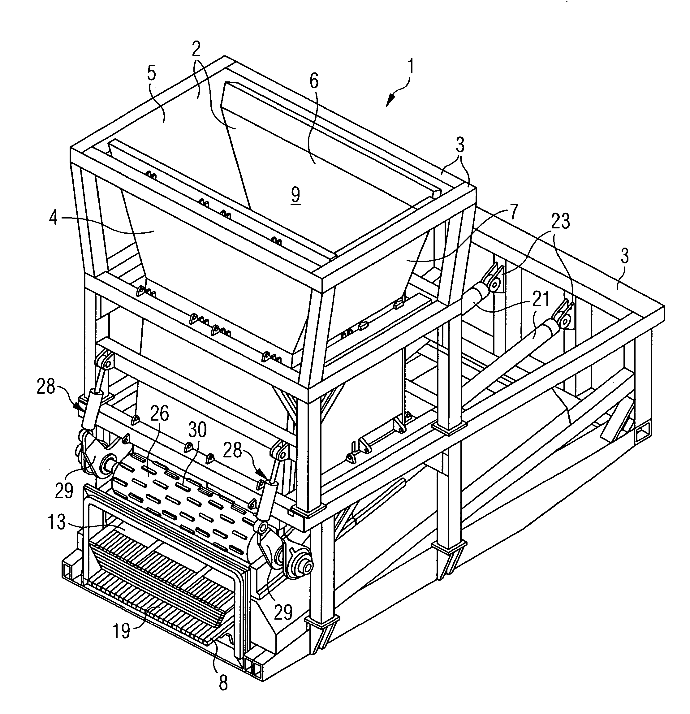
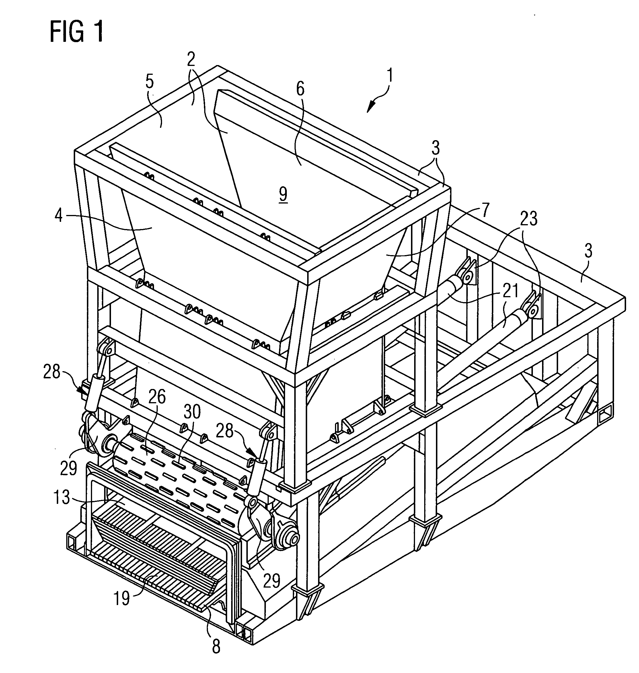
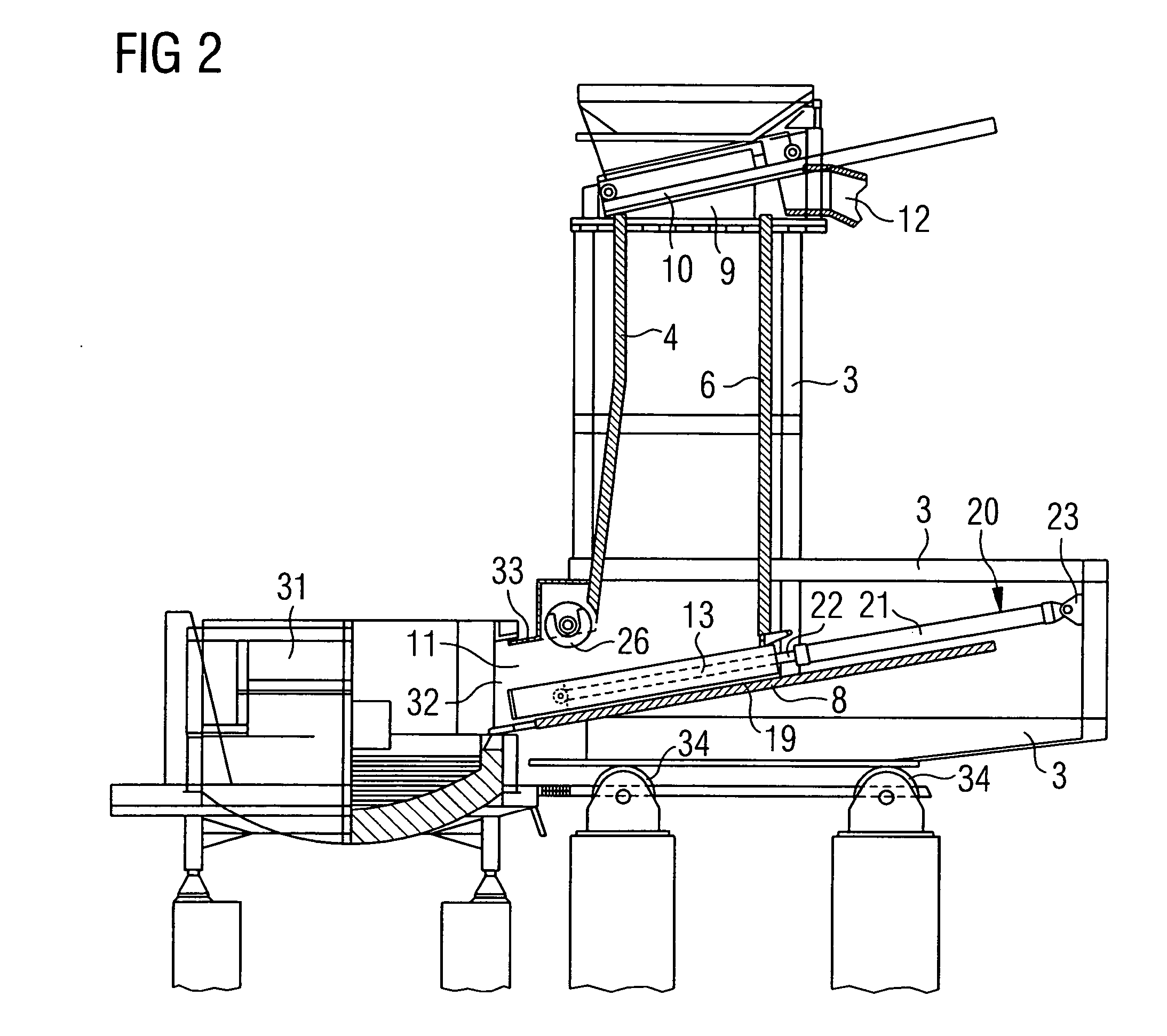
[0020] The shaft-shaped charging stock preheater 1 shown in perspective in FIG. 1 for the preheating of the charging stock to be charged into a melting vessel comprises a shaft 2 with shaft walls 4, 5, 6, 7 held in a frame structure 3. Also provided are a lower shaft floor 8 and an upper charging stock inlet opening 9 that is closable by a cover 10 (See FIG. 2). In the lower area of the shaft 2, in the side wall 4 appearing on the left in the diagram according to FIG. 2, a discharge opening 11 for the charging stock is provided, which simultaneously forms a gas inlet for heating gas that can be utilized to heat the charging stock present in the shaft. A gas outlet 12 is present in the upper area of the shaft 2.

[0021] The charging stock preheater also contains a pusher 13, which is shown in FIGS. 3-5 in various partial and enlarged views. The pusher 13 has a top surface 14, a bottom surface 15, an end surface 16 transverse to the pushing direction, and two lateral surfaces 17, 18 pa...


PUM

PropertyMeasurementUnit
inclination angleaaaaaaaaaa
convergence angleaaaaaaaaaa

Abstract

To facilitate a trouble-free charging of scrap metal having differing constitutions, such as light and heavy scrap metal, from a lower discharge opening of a shaft-shaped charging device or a charging stock preheater (1) into a melting vessel by a pusher (13), the lateral surfaces of the pusher (13) are formed so as to converge from the upper side to the lower side and the actuating device (2) of the pusher (13) is pivotably supported in a frame structure (3) about a horizontal axis. In addition, the upper boundary of the discharge opening for the charging stock from the shaft (2) is preferably formed by a horizontal, rotatably supported roller (26), more preferably with engaging elements (30) distributed around the circumferential surface. Sections of the charging device that are severely mechanically stressed are preferably formed by steel billet sections connected to form a structural unit.

Description

CROSS-REFERENCE [0001] This application is the US national phase of International Application No. PCT / EP2004 / 013355 filed Nov. 25, 2004, which claims priority to German patent application no. 103 55 549.8 filed Nov. 27, 2003.1. TECHNICAL FIELD [0002] The invention relates to a charging device for charging stock into a melting vessel. The invention relates more particularly to a charging device of said type designed as a charging stock preheater, in which the material to be charged into the melting vessel is preheated by flowing heated gases through the preheater, preferably the hot exhaust gases from the melting furnace that will be charged with the stock material. 2. BACKGROUND ART [0003] A charging device of this type designed as a charging stock preheater is known, for example, from JP 7-180975 A. [0004] In charging devices of this type, problems arise when, during the charging of steel scrap, charging stock of widely varying size, such as in the form of chips, railway rails, eng...

Claims


Application Information

Patent Timeline
Patent Type & Authority Applications(United States)
IPC IPC(8): C21B7/16F27B3/18F27D3/04F27D3/06F27D13/00
CPCF27B3/186F27D13/002F27D3/06F27D3/04Y10S266/901F27D13/00F27D3/00F27B3/18
Inventor FUCHS, GERHARD
Owner FUCHS TECH
Why Eureka
Try Eureka