
Dual surveillance camera system

a technology of surveillance camera and camera body, applied in the field of security cameras, can solve the problems of bulky security systems and difficult placement in a discreet, unobtrusive way

Inactive Publication Date: 2007-01-18
BOSCH SECURITY SYST INC
View PDF5 Cites 19 Cited by
  • Summary
  • Abstract
  • Description
  • Claims
  • Application Information

AI Technical Summary

Benefits of technology

[0004] This invention provides a surveillance system having two specialized surveillance cameras with corresponding specialized illuminators in a dual compartment container that eliminates internal light reflection problems by an arrangement which concomitantly renders the system more compact and suited to unobtrusive placement. Considerable heat is generated by the specialized illuminators, requiring a heat sink to preserve illuminator life expectancy and to prevent the adjacent cameras from being adversely affected by the heat. Another feature enabling the system to work in its compact form despite the heat from the illuminators is that the protective case itself is adapted to be a heat sink for the illuminators.
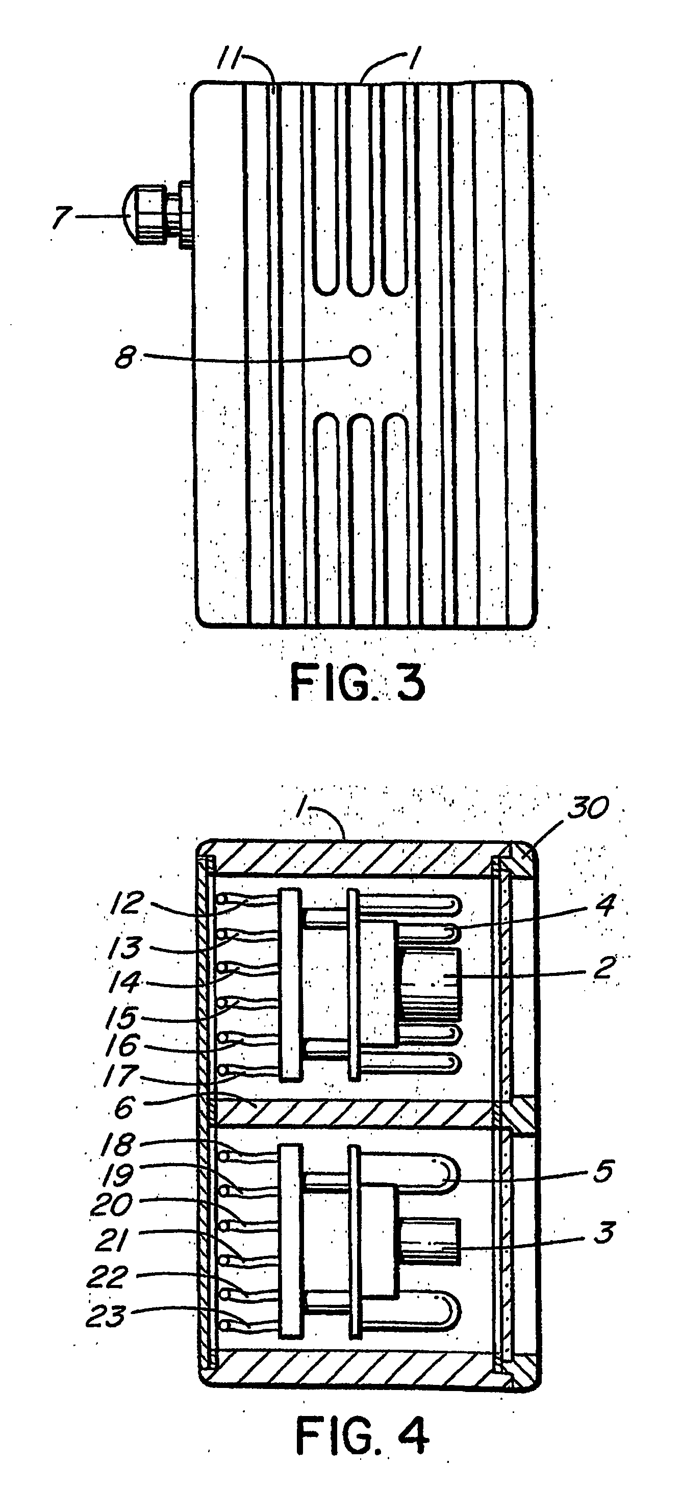
[0005] The system achieves its compactness by having a first camera adapted for recording images under a first type of illumination, a second camera adapted for recording images under a second type of illumination, a first illuminator for providing the first type of illumination, a second illuminator for providing the second type of illumination, and two compartments, each having a translucent pane. The panes substantially face the same way. The first compartment contains the first camera and the second illuminator. The second compartment contains the second camera and the first illuminator. The first and second compartments are separated from each other by an opaque wall preventing light from the first illuminator originating in the second compartment from reflecting off the second translucent pane directly to the first camera and preventing light from the second illuminator originating in the first compartment from reflecting off the first translucent pane directly to the second camera.
[0007] In one preferred embodiment, the first camera is a colour camera for observation under visible light, the second camera is a monochrome camera for observation under infrared illumination, the first illuminator is a visible light illuminator, and the second illuminator is an infrared illuminator. The first and second compartments are formed by a box with a dividing wall, the box being formed with cooling fins of heat-conducting material. These features enable a working, lasting, dual surveillance camera and dual illuminator system in which the compartments are small enough resemble a minature speaker cabinet for unobtrusive yet stylish placement. Alternatively the compactness can be used to have a working, lasting, dual surveillance camera and dual illuminator system fit covertly behind an electrical switch box decor cover plate.
[0008] The benefits of this dual camera system of imaging are enhanced if the colour camera has a lens optimized for colour viewing with infra-red filtering, and the monochrome camera has a lens optimized for monochrome viewing with visible light filtering. The monochrome camera could be supercharged electronically for infrared sensitivity, with the infrared illuminator giving illumination in the range of from 805 to 995 nanometers of electromagnetic radiation. Although it is possible for the electronics of a colour CCTV camera to share a lens with a monochrome CCTV camera, each camera in the present system should have its own lens, and each of the cameras can then have separate varifocal control to enable a switch of mode from day to night operation without a focal shift of the lens, which would otherwise be required when shifting from colour to monochrome camera output to obtain the best imaging.

Problems solved by technology

The combination of versatile camera systems with protective cases has resulted in many such security systems being bulky and difficult to place in a discreet, unobtrusive way.

Method used


Image

  • Dual surveillance camera system
  • Dual surveillance camera system
  • Dual surveillance camera system

Examples


Embodiment Construction

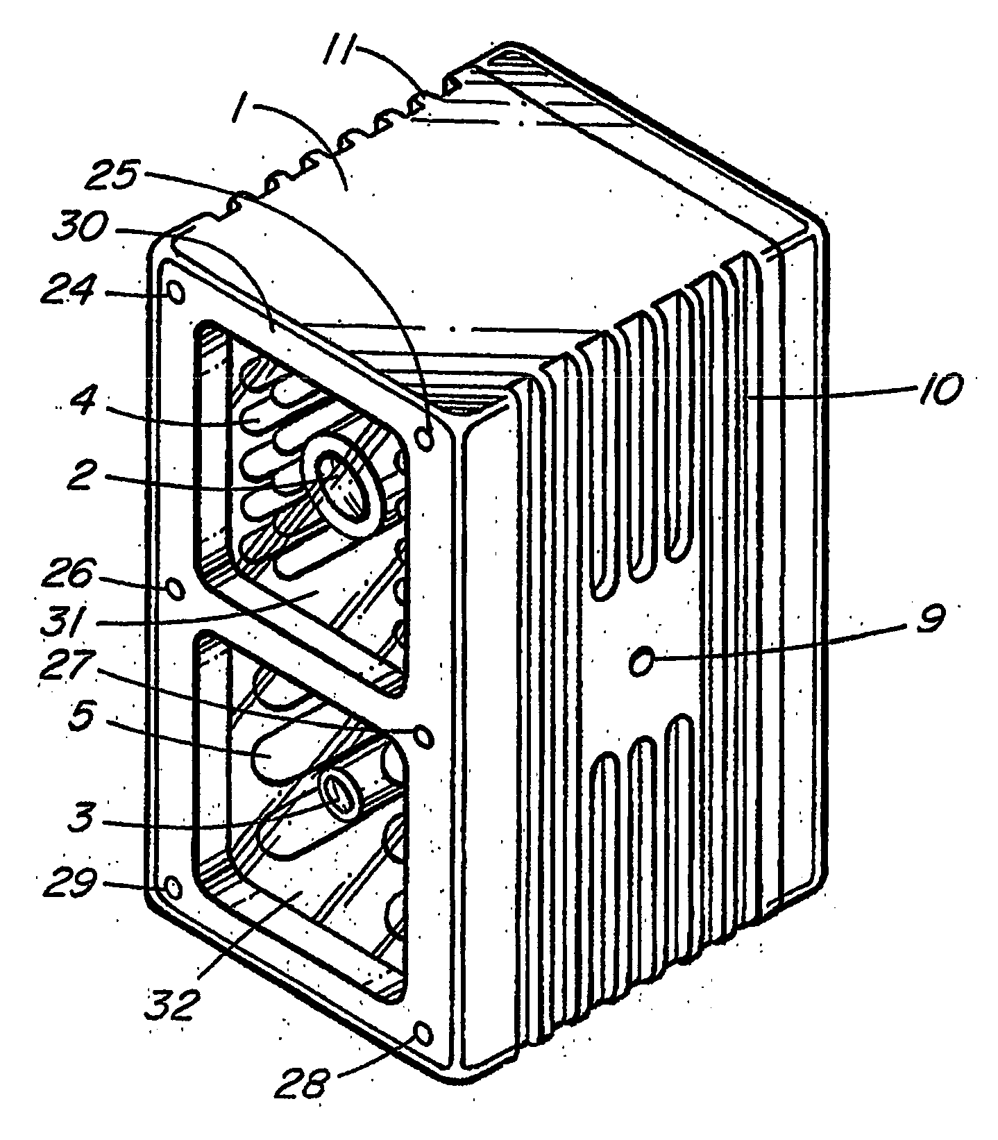
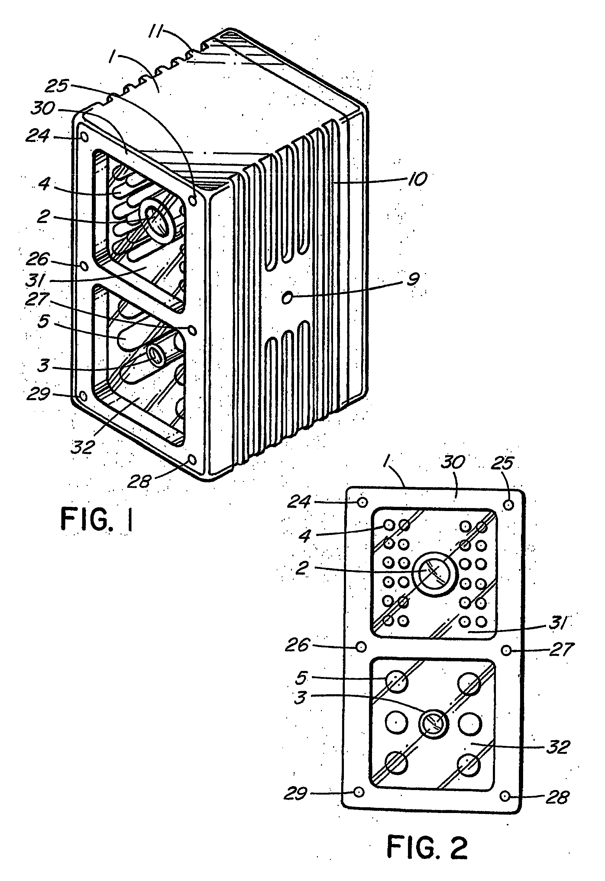
[0013] Referring to FIGS. 1 and 2, the dual surveillance camera system case 1 having in its top compartment a first (colour) camera 2, complete with a lens optimized for colour with infra-red filtering, adapted for recording images under a first type of illumination provided by the first (visible light) illuminator 5 in the bottom compartment, and having in its bottom compartment a second (monochrome) camera 3, complete with a lens optimized for monochrome viewing with visible light filtering, for recording images under a second type of illumination provided by the second (infrared) illuminator 4.

[0014] A cover 30 secures translucent panes 31 and 32 over the respective cameras and illuminators, with screws at 24 through 29. The case 1 is made of heat-conductive material and has integral cooling fins as at 10 and 11 to increase surface area contact with surrounding air.

[0015] The infrared illuminator 4 and the visible light illuminator 5 preferably comprise banks of infrared and vi...


PUM


Abstract

A surveillance system having two specialized surveillance cameras with corresponding specialized illuminators is provided in a dual compartment container that eliminates internal light reflection problems by separating each camera and corresponding illuminator while combining each camera with an alternate illuminator, rendering the system more accurate, yet more compact and suited to unobtrusive placement. Considerable heat is generated by the specialized illuminators, requiring a heat sink to preserve illuminator life expectancy and to prevent the adjacent cameras from being adversely affected by the heat. Another feature enabling the system to work in its compact form despite the heat from the illuminators is that the protective case itself is adapted to be a heat sink for the illuminators.

Description

BACKGROUND OF THE INVENTION [0001] This invention relates to security cameras and the obtaining of optimal images under varying ambient light conditions. In some circumstances, it is most effective to obtain visible light images. In other situations, such as poor visibility due to smoke or fog, infrared images give the best information about people and objects in the surveillance situation. Versatility and adaptability of the security system to varying conditions is desired. [0002] With security cameras it is usual to place a protective translucent pane or dome over the camera and illuminator, to guard it against the elements or intentional damage by intruders or others who do not wish to be observed. [0003] The combination of versatile camera systems with protective cases has resulted in many such security systems being bulky and difficult to place in a discreet, unobtrusive way. SUMMARY OF THE INVENTION [0004] This invention provides a surveillance system having two specialized su...

Claims


Application Information

Patent Timeline
IPC IPC(8): H04N7/18H04N5/33F21V33/00G03B15/03G03B17/55G03B29/00G08B
CPCG08B13/19626G08B13/19636G08B13/19643H04N7/181H04N5/2354H04N5/33H04N5/332H04N5/2256H04N23/56H04N23/74H04N23/20H04N7/18H04N23/11
Inventor GIN, JACKHSU, DAN
Owner BOSCH SECURITY SYST INC
Learn More