Control Panel Assembly

a technology of control panel and assembly, which is applied in the direction of color television details, color signal processing circuits, electrical apparatus, etc., can solve the problems of reducing the aesthetic feel of the control button, preventing smooth operation, and the button tilting about the mechanical switch

Inactive Publication Date: 2007-01-18
ACCESS BUSINESS GRP INT LLC
View PDF4 Cites 15 Cited by
  • Summary
  • Abstract
  • Description
  • Claims
  • Application Information

AI Technical Summary

Benefits of technology

[0005] The present invention provides an illuminated control button with an eccentric switch and a button spring configured to substantially balance the mechanical resistance, of the switch when the button is depressed.

Problems solved by technology

If the button is off-center, pushing, the center of the control button may cause the button to tilt about the mechanical switch.
This tilting reduces the aesthetic feel of the control button and may cause the control button to bind, thereby preventing smooth operation.
This may reduce the aesthetic appeal of the button and may make is difficult to see the entire symbol.
Unfortunately, a conventional control button assembly does not provide sufficient space for both the switch and the light source to be mounted at the center of the control button.

Method used


Image

  • Control Panel Assembly
  • Control Panel Assembly
  • Control Panel Assembly

Examples


Embodiment Construction

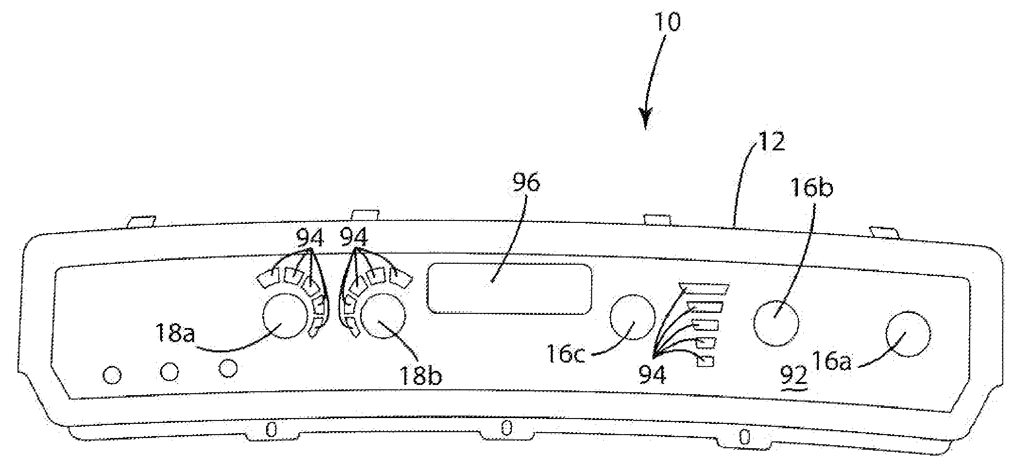
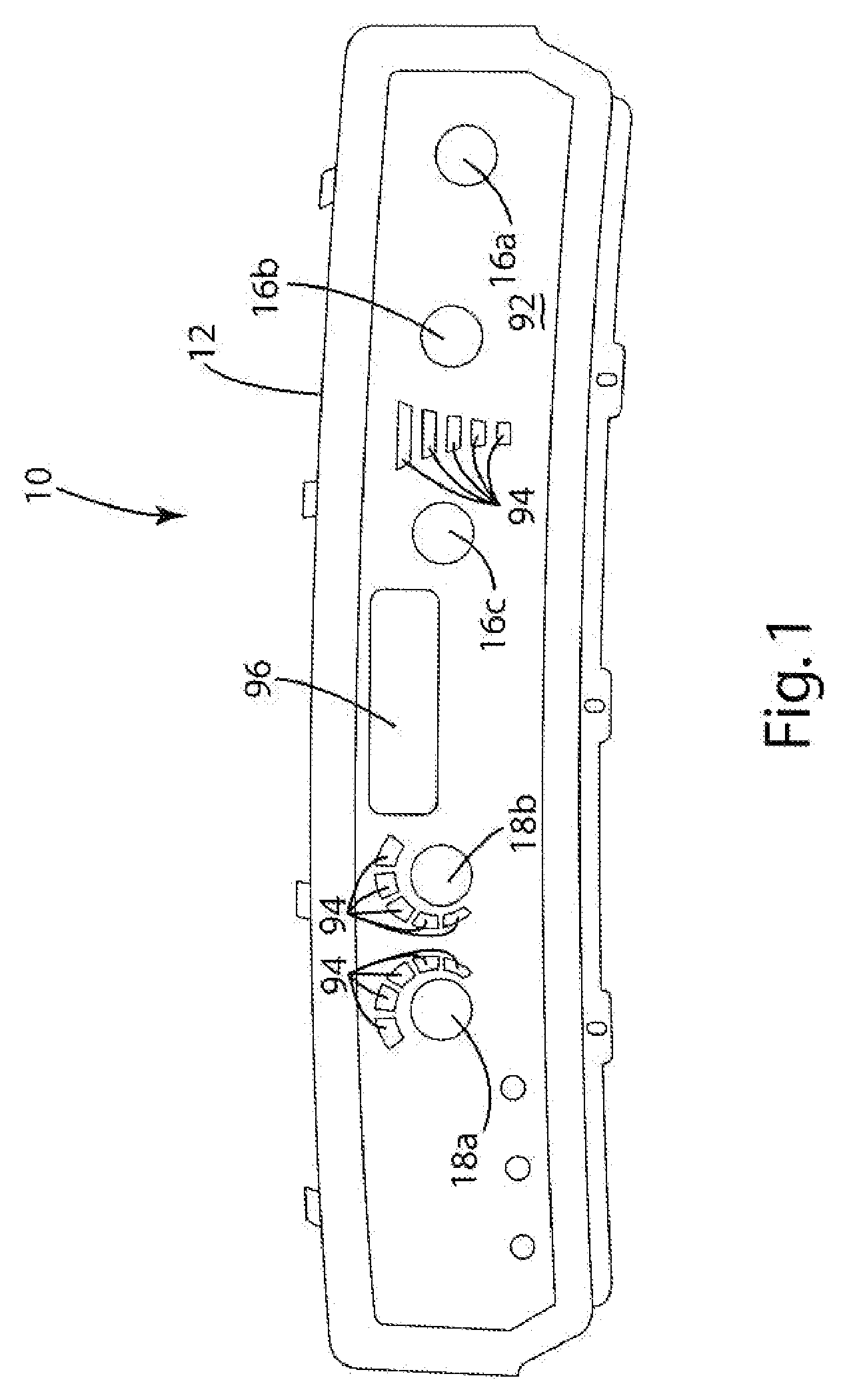
[0031] A control button assembly in accordance with one embodiment of the present invention is shown in FIGS. 1-12. The present invention is described in connection with a control panel assembly 10 (See FIG. 1) for an air treatment system (not shown). The present invention is, however, not restricted to use with air treatment systems. Rather, the present invention can be readily incorporated into the controls of essentially any type of system.

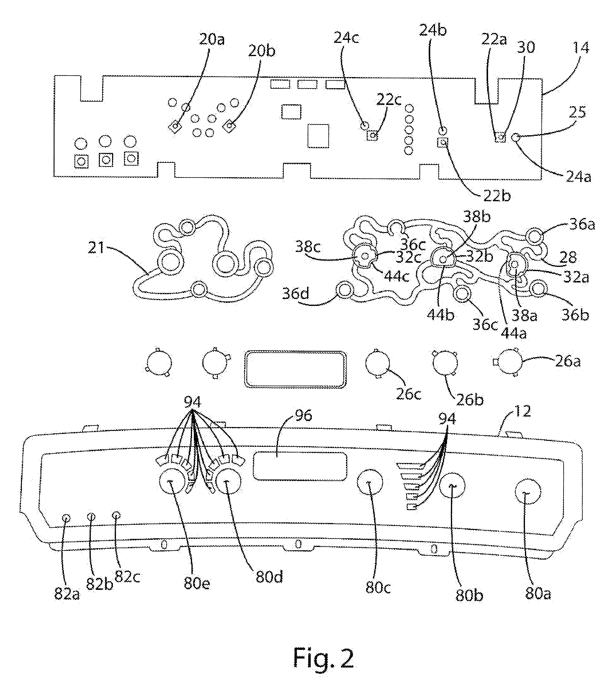
[0032] The control panel assembly 10 generally includes a control panel 12, a circuit board 14 and a plurality of control button assemblies 16a-c and 18a-b (See FIGS. 1 and 2). In the illustrated embodiment, the control panel 12 is generally conventional. As perhaps best shown in FIG. 2, the control panel 12 defines a plurality of button openings 80a-e configured to receive the various button assemblies 18a-b and 16a-c. The control panel 12 also defines a plurality of reset openings 82a-c that provide access to filter reset switches 84a-c moun...


PUM


Abstract

An illuminated control button with an eccentric switch and a button spring configured to substantially balance the mechanical resistance of the switch when the button is depressed. The switch may be a conventional push-button switch having a stem directly contacting a portion of the control button. The button spring may include an integral reflector and may have a rim that defines a surface engaging the button. The control button may include a fixed light source and the reflector may move about the light source when the control button is depressed. The present invention also provides a control button with a light source at least partially contained within an integrating sphere. In one embodiment, the integrating sphere includes a somewhat cup-shaped diffusely reflective surface that cooperates with a diffusely reflective surface on the back surface of the button to substantially evenly distribute light from the light source throughout the integrating sphere.

Description

BACKGROUND OF THE INVENTION [0001] The present application claims the benefit of U.S. Provisional Application No. 60 / 699,162 filed Jul. 14, 2005.[0002] The present invention relates to control panels and more particularly to illuminated electronic control panels. [0003] Illuminated control buttons are in wide spread use. A conventional control button includes a light source and a switch. A transparent or translucent window is typically formed in the button in the form of an icon, letter(s), number(s) or other symbols. Often, the light source (such as an LED) and switch (such as a push-button micro switch) are mounted to a circuit board positioned below the control button. It is desirable to center the switch on the button so that when the button is depressed, the mechanical resistance of the switch does not cause the button to cant or twist. If the button is off-center, pushing, the center of the control button may cause the button to tilt about the mechanical switch. This tilting r...

Claims


Application Information

Patent Timeline
Patent Type & Authority Applications(United States)
IPC IPC(8): H04N9/73
CPCH01H2217/01H01H13/023H01H13/02H01H13/14H01H13/28
Inventor PIPPEL, BRADLEY J.LAUTZENHEISER, TERRY L.NIEZGODA, THOMAS A.
Owner ACCESS BUSINESS GRP INT LLC
Why Eureka
Try Eureka