
Mechanical spring component for use in memory device

a technology of mechanical springs and memory devices, which is applied in the direction of coupling device connections, coupling protective earth/shielding arrangements, electrical apparatus casings/cabinets/drawers, etc., can solve the problems of inconvenient use for users, inability to provide optimal conditions for a computer memory device, and damage to electrical contacts of portable memory devices. , to achieve the effect of improving user convenien

Inactive Publication Date: 2007-01-18
IMATION
View PDF24 Cites 51 Cited by
  • Summary
  • Abstract
  • Description
  • Claims
  • Application Information

AI Technical Summary

Benefits of technology

[0006] Accordingly, one object of the present invention is to provide improved designs for portable computer memory devices.
[0007] Another object of the present invention is to improve the convenience for users to protect data connectors and other sensitive parts on a portable computer memory device.
[0008] Another object of the present invention is to create a user friendly design that is intuitive for the user to operate.
[0009] Another object of the present invention is to create memory device that allows for one hand operation to extend and retract the data connector.

Problems solved by technology

These storage or transport environments, however, often fail to provide the optimal conditions for a computer memory device.
For example, a user's pocket may contain contaminants such as lint or other debris from everyday wear.
The electrical contacts of the portable memory device may be subject to damage.
These caps and covers, however, are typically separate devices that may be lost or misplaced, leaving the electrical contacts unprotected.
Loss of these device may subject the portable memory device to damage and loss of information.
The use of caps and covers also inconveniences a user, bring in more parts into play.

Method used


Image

  • Mechanical spring component for use in memory device
  • Mechanical spring component for use in memory device
  • Mechanical spring component for use in memory device

Examples


Embodiment Construction

[0023] It is to be understood that both the foregoing general description and the following detailed description are exemplary and explanatory only and are not restrictive of the invention, as claimed. It may be noted that, as used in the specification and the appended claims, the singular forms “a”, “an” and “the” include plural referents unless the context clearly dictates otherwise. Thus, for example, reference to “a material” may include mixtures of materials and the like. References cited herein are hereby incorporated by reference in their entirety, except to the extent that they conflict with teachings explicitly set forth in this specification.

[0024] In this specification and in the claims which follow, reference will be made to a number of terms which shall be defined to have the following meanings:

[0025]“Optional” or “optionally” means that the subsequently described circumstance may or may not occur, so that the description includes instances where the circumstance occu...


PUM


Abstract

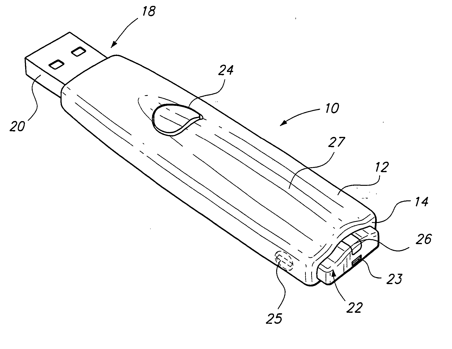
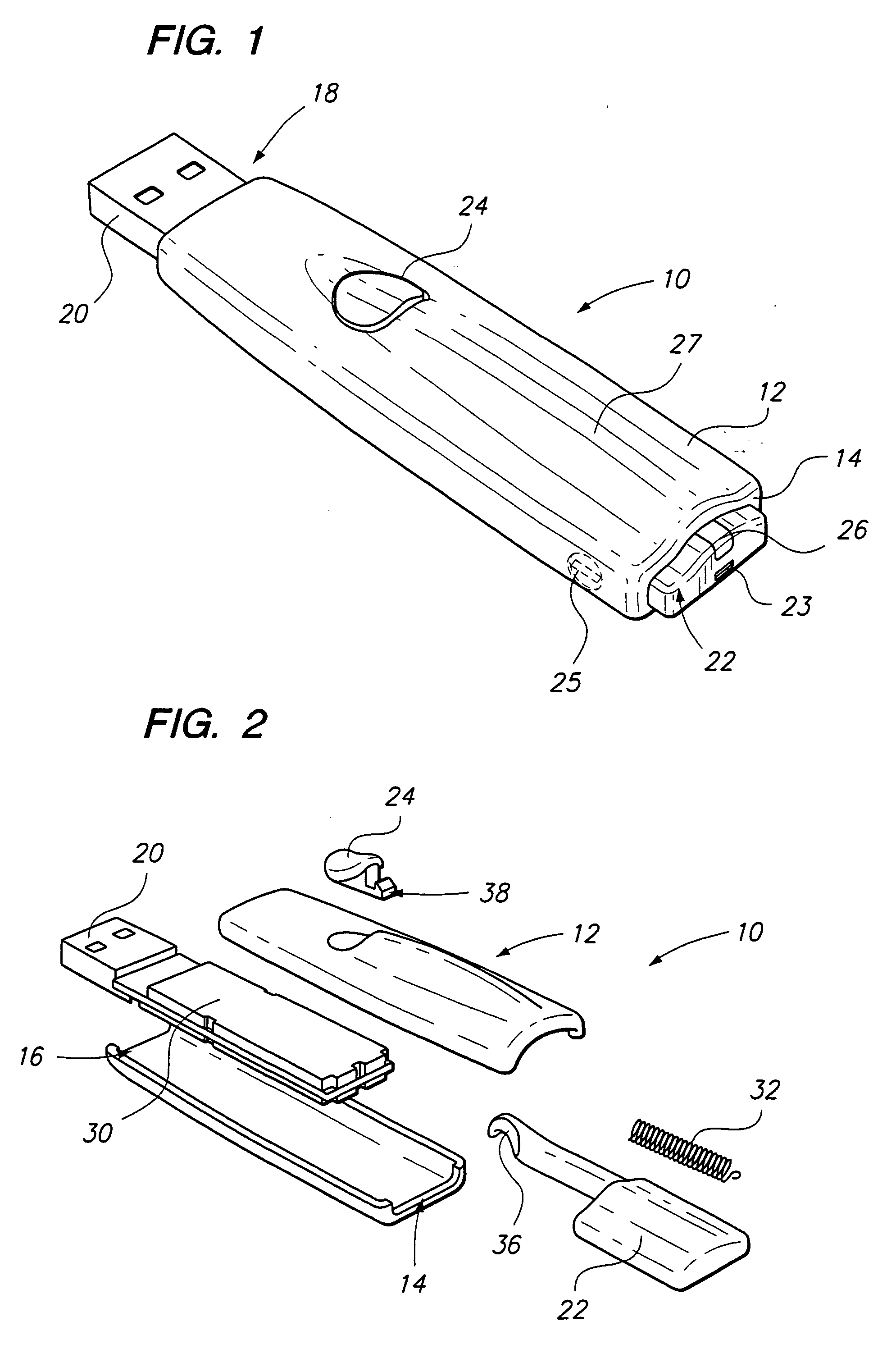
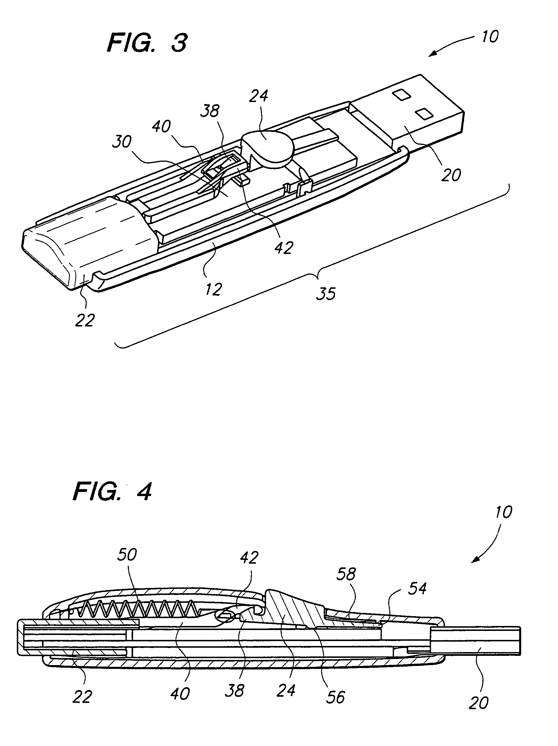
Methods and apparatus are provided for an improved portable memory device. In one embodiment, a portable memory device is provided comprising a housing having a proximal opening and a distal opening. A slidable unit may be at least partially mounted in the housing. The slidable unit may comprise of a memory device slidably mounted in the housing, wherein the memory device has a data connector mounted on one end and a push button on the other end. A resilient member may be coupled to the slidable unit. Moving the slidable unit from a first position to a second position will simultaneously extend the data connector from the housing while also loading the resilient member to urge the data connector back into the housing. The portable memory device may include a latch coupled to the housing for holding the slidable unit in the second position. In the present embodiment, a user may press a release button so that the latch will allow the connector to be automatically drawn back into the housing.

Description

BACKGROUND OF THE INVENTION [0001] 1. Field of the Invention [0002] This invention relates to computer memory devices and more specifically, mechanical components for use with computer memory devices. [0003] 2. Description of Related Art [0004] Today's computer memory devices are becoming more compact while providing even more storage capacity. This trend has grown to encompass all types of personal computing devices and computer memory devices, including but not limited to portable computer memory peripherals such as universal serial bus (USB) drives. Some embodiments of these drives are now capable of holding gigabytes of information in a relatively small form factor. These USB drives are compact, rewritable, and can quickly transfer large files between devices with a USB port. This has allowed a great degree of flexibility in business environments where users in a meeting or other setting can easily transfer files between various computing devices. [0005] Due to their convenient ...

Claims


Application Information

Patent Timeline
IPC IPC(8): H01R13/648
CPCH01R13/4538H05K5/0278H01R13/60
Inventor LOFTUS, JOHN
Owner IMATION
Features
  • Generate Ideas
  • Intellectual Property
  • Life Sciences
  • Materials
  • Tech Scout
  • Unparalleled Data Quality
  • Higher Quality Content
  • 60% Fewer Hallucinations
Learn More