Cardiac harness delivery device and method of use

a delivery device and cardiac harness technology, applied in the field of cardiac harness delivery devices and methods, can solve the problems of difficult minimally invasive deployment of cardiac harnesses, and achieve the effect of reducing the effectiveness of predetermined bends and eliminating the possibility of distal ends flattening during storag

Inactive Publication Date: 2007-01-18
PARACOR MEDICAL
View PDF31 Cites 36 Cited by
  • Summary
  • Abstract
  • Description
  • Claims
  • Application Information

AI Technical Summary

Benefits of technology

[0013] In another embodiment, the present invention involves an assembly for delivering a cardiac harness including an elongate body having a proximal portion and a distal portion. The body has a cavity sized to contain the harness in a compacted configuration. A plurality of elongate push rods are longitudinally movable with respect to the elongate body and to deliver and mount the cardiac harness onto the heart. The elongate push rods have a distal end having a predetermined bend to form an atraumatic tip so that the distal end of the push rods do not dig into or otherwise harm the surface of the heart. During aging and storage, the curvature in the distal ends in the elongate push rods can flatten, thereby reducing the effectiveness of the predetermined bend. In this embodiment, the distal ends of the push rods can be bent by the doctor in order to return the predetermined bend in the distal end of the push rod. Further, during storage, a donut-shaped device or tip spreader is formed around the distal ends of the push rods in order to maintain the predetermined bend and to eliminate the possibility of the distal ends flattening during storage.

Problems solved by technology

In these instances, it is difficult to deploy a cardiac harness minimally invasively since the initial turn or bend to push the harness onto the heart can be anywhere from 10° to 90°.

Method used


Image

  • Cardiac harness delivery device and method of use
  • Cardiac harness delivery device and method of use
  • Cardiac harness delivery device and method of use

Examples


Embodiment Construction

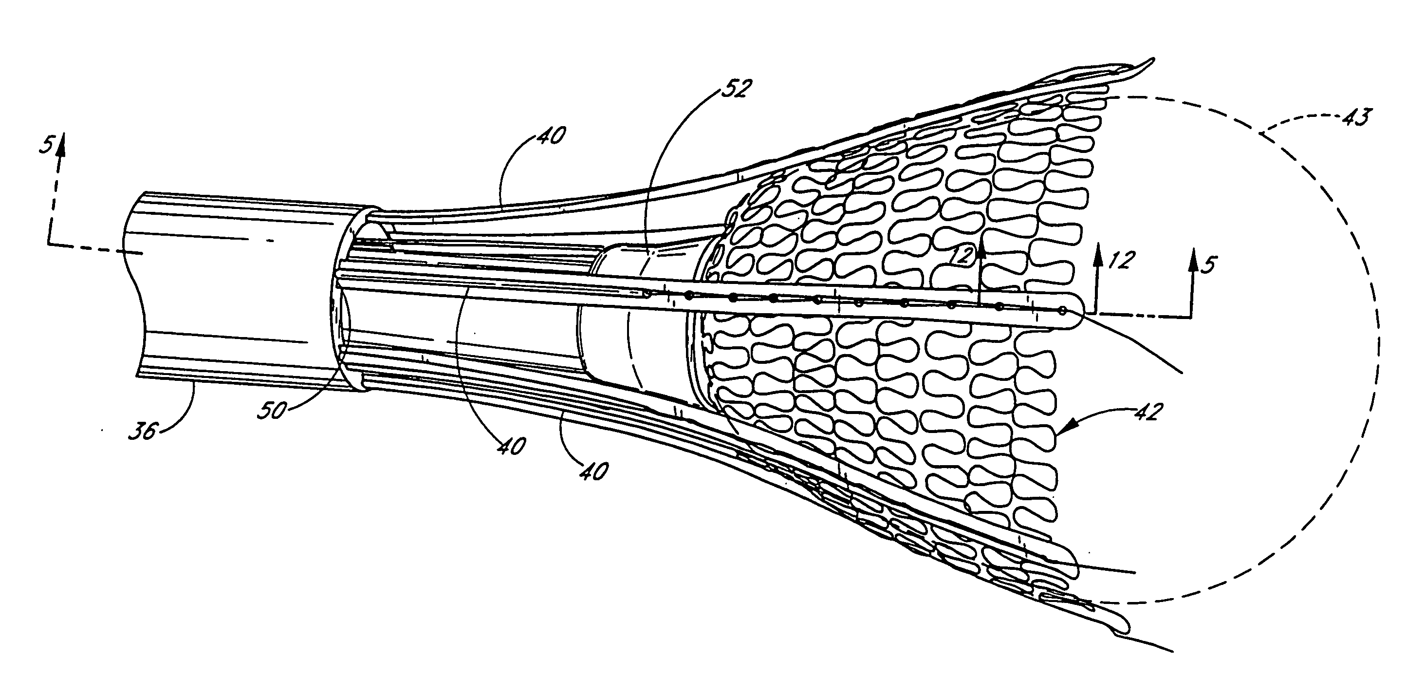
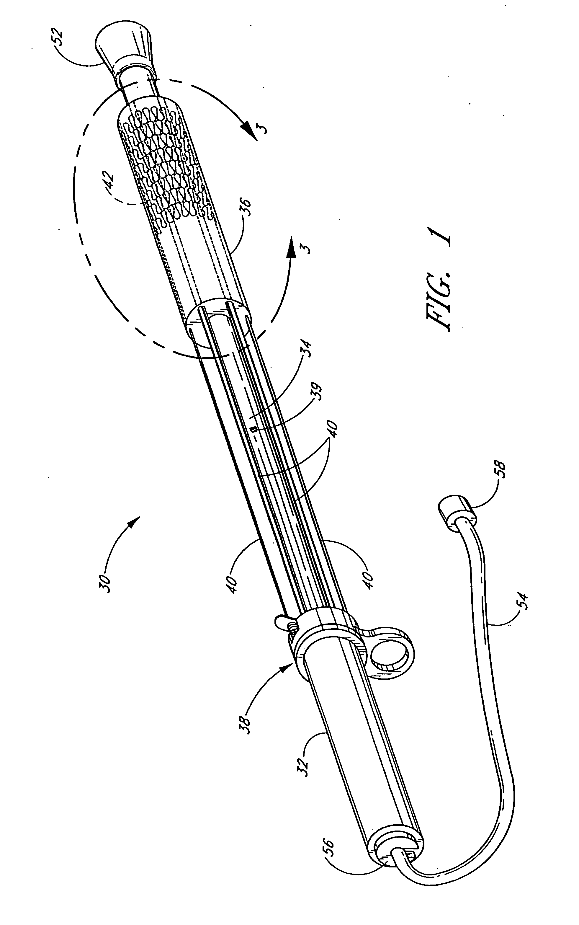
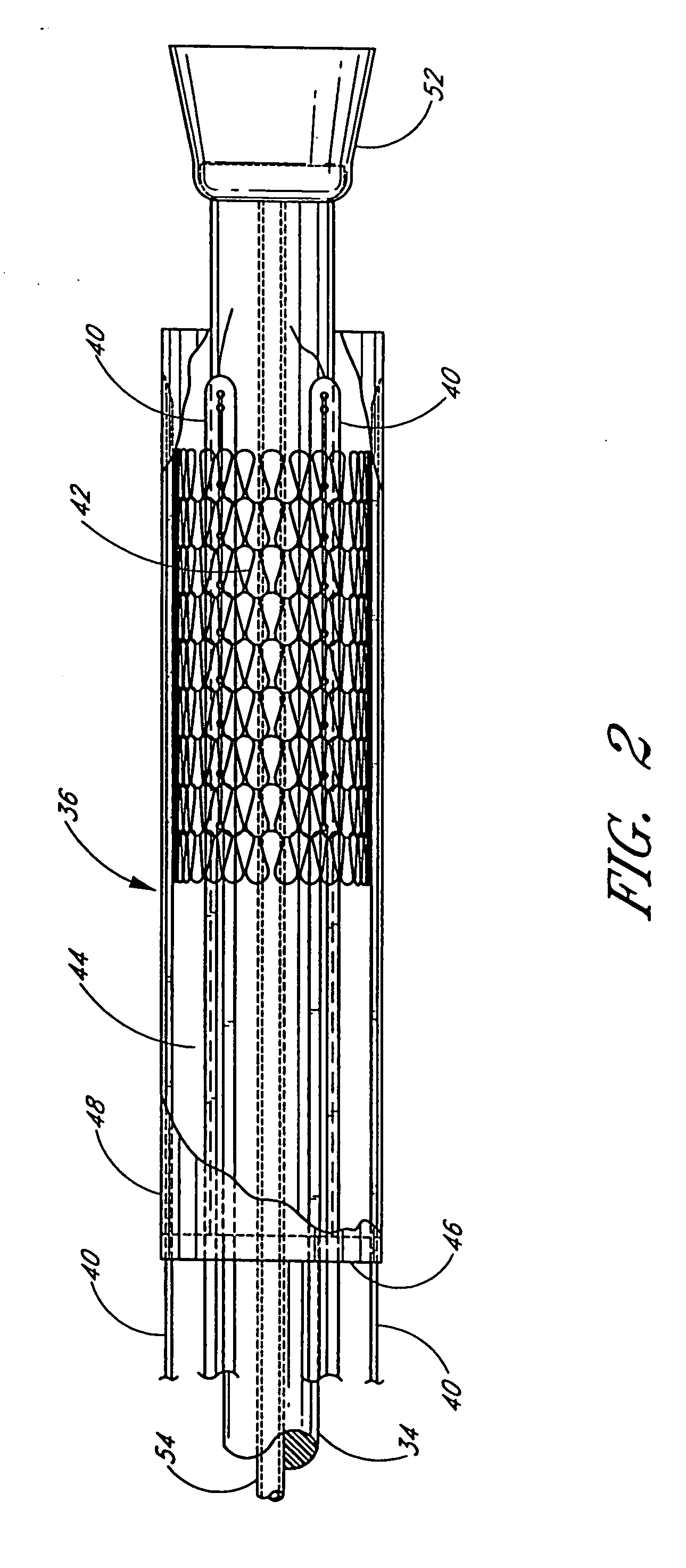
[0078]FIGS. 1-11 illustrate a preferred embodiment of a cardiac harness delivery device, which is generally referred to by the reference numeral 30. In a preferred embodiment, the delivery device 30 is configured to releasably support a cardiac reinforcement device (CRD), such as a cardiac harness, and assist in the advancement of the cardiac harness over the heart of a patient. Once the cardiac harness is positioned on the heart, the delivery device 30 preferably is configured to release the harness and be retractable without causing undesired shifting of the cardiac harness relative to the heart.

[0079] In the illustrated arrangement, the delivery device 30 permits delivery of a cardiac harness in a minimally invasive manner. That is, preferably the device 30 permits accurate delivery, positioning, and release of the cardiac harness through a relatively small incision in a patient. However, the preferred, or alternative, embodiments of the delivery device 30 may also be used to de...


PUM


Abstract

A delivery system for delivering and mounting a cardiac harness on a heart including an elongate body having a proximal portion and a distal portion. The body includes a cavity sized to contain the cardiac harness in a compacted configuration and also includes a plurality of elongate push rods movable with respect to the body. The cardiac harness is releasably connected to the push rods such that, advancement of the push rods in a distal direction moves the cardiac harness from a compacted configuration, within the cavity, to an expanded configuration, outside the cavity. The push rods are configured to have varying stiffness along their length to provide sufficient flexibility to bend up to 90° to advance the cardiac harness onto the heart.

Description

CROSS-REFERENCES TO RELATED APPLICATIONS [0001] The present application is a continuation-in-part of U.S. Ser. No. 10 / 715,150 filed Nov. 17, 2003 which is related to, and claims priority from, U.S. Provisional Patent Application No. 60 / 427,079, filed Nov. 15, 2002, the entirety of each of which is hereby incorporated by reference.FIELD OF THE INVENTION [0002] The present invention relates generally to a device and method for delivering a cardiac harness onto the heart of a patient. BACKGROUND OF THE INVENTION [0003] Congestive heart failure (“CHF”) is characterized by the failure of the heart to pump blood at sufficient flow rates to meet the metabolic demand of tissues, especially the demand for oxygen. It has been determined that a passive wrap, or cardiac harness, may increase the efficiency of a heart affected by congestive heart disease. While advances have been made in cardiac harness technology, a satisfactory device and method for delivering and positioning the cardiac harne...

Claims


Application Information

Patent Timeline
Patent Type & Authority Applications(United States)
IPC IPC(8): A61F13/00A61F2/00A61B17/00A61B17/30
CPCA61B17/00234A61B2017/00238A61B2017/00243A61F2002/2484A61B2017/308A61B2018/00392A61F2/2481A61B2017/00247
Inventor LAU, LILIPWALLIN, JOSHUA
Owner PARACOR MEDICAL
Why Eureka
Try Eureka