Blood pressure measuring apparatus

a technology of measuring apparatus and blood pressure, which is applied in the field of blood pressure measuring apparatus, can solve the problems of long measurement time, difficult to attach sensors or cuffs to two locations for measuring pulse waves, and use of ecgs, etc., and achieve the effect of simple method and continuous measuremen

Active Publication Date: 2007-01-18
FUKUDA DENSHI CO LTD
View PDF12 Cites 31 Cited by
  • Summary
  • Abstract
  • Description
  • Claims
  • Application Information

AI Technical Summary

Benefits of technology

[0008] The present invention has been made in consideration of the problems of the prior art as described above, and has as its object to provide blood pressure measuring apparatus capable of continuously measuring blood pressure by a simple method.
[0010] In the present invention having the above arrangement, the pulse wave propagation time is measured using the progressive wave component and reflected wave component of a pulse wave measured in one location, and blood pressure is obtained on the basis of this pulse wave propagation time. This obviates the need to measure pulse waves in two locations, so the measurement is easy. In addition, the pulse wave propagation time is measured on the basis of only a pulse wave. Therefore, it is unnecessary to take account of the influence of the preejection period which is required when an ECG is to be used instead of a pulse wave. As a consequence, accurate measurement results can be obtained.

Problems solved by technology

To measure the pulse wave propagation time, however, pulse waves must be measured in different locations, so the measurement requires a long time.
Also, it is sometimes difficult to attach sensors or cuffs for measuring pulse waves to two locations.
Unfortunately, the use of an ECG has a problem of the measurement accuracy.
This presently makes the preejection period hard to correct.
Accordingly, it is difficult to obtain results more accurate than when blood pressure is calculated from the propagation time obtained from two pulse waves.

Method used


Image

  • Blood pressure measuring apparatus
  • Blood pressure measuring apparatus
  • Blood pressure measuring apparatus

Examples


Embodiment Construction

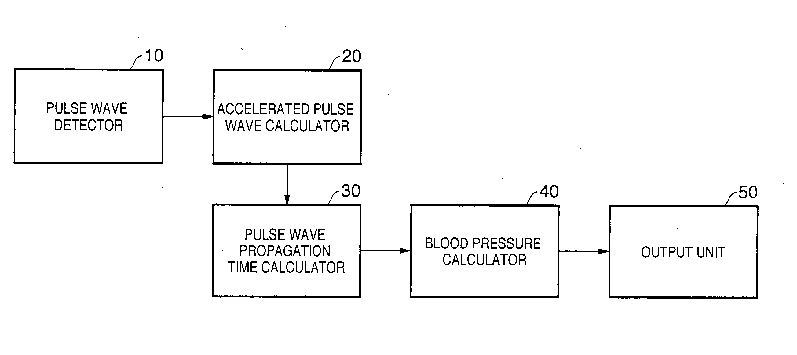
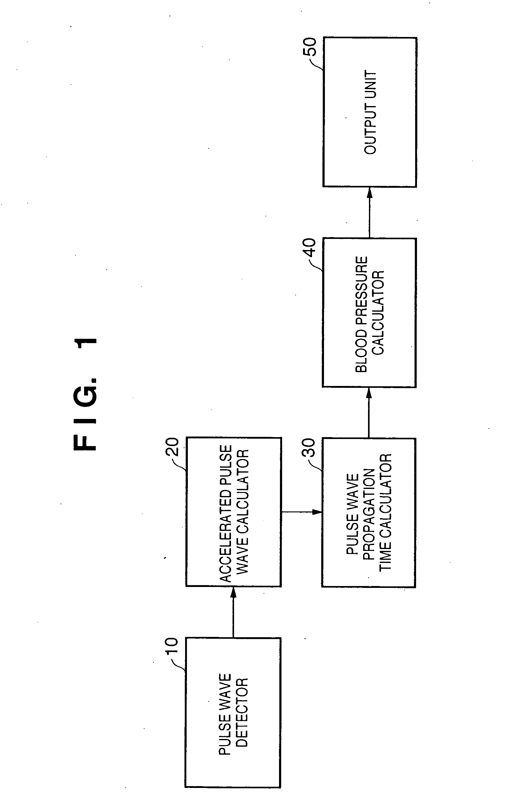
[0018] A preferred embodiment of the present invention will now be described in detail in accordance with the accompanying drawings.

[0019] First, the principle of the present invention will be explained below.

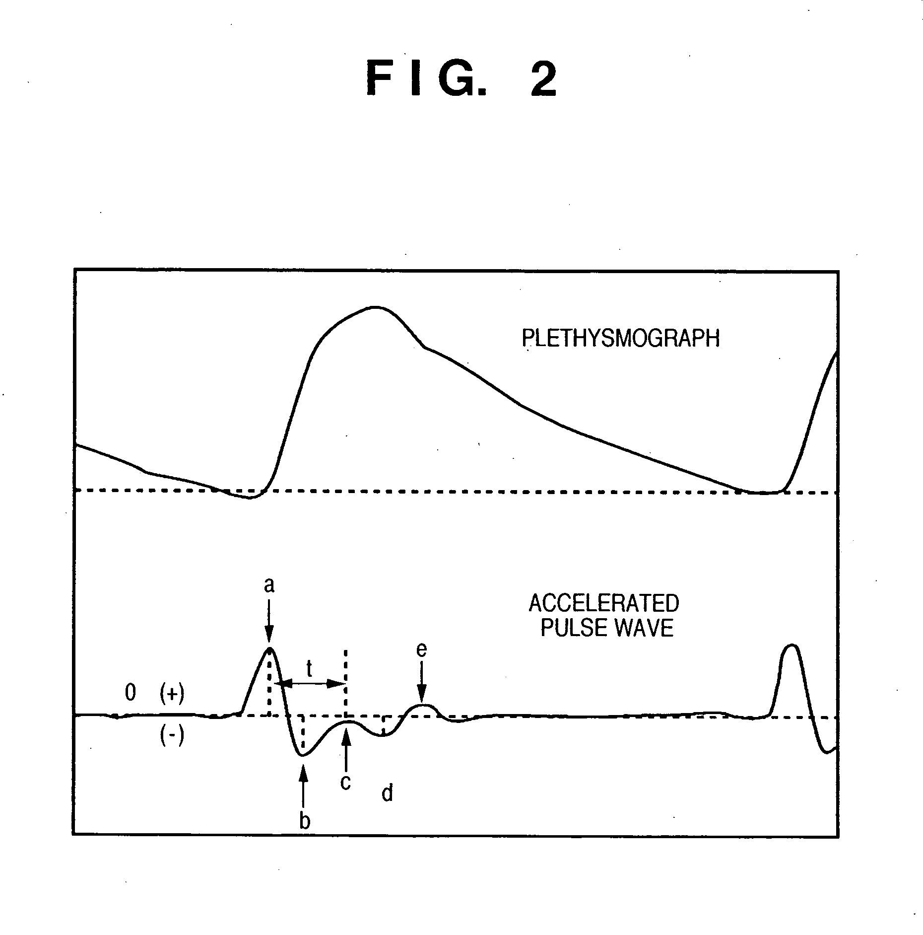
[0020] The waveform of a pulse wave observed in the aortic root differs from those of pulse waves observed in other locations, and various researches and analyses have been conventionally performed on the pulse wave propagation mechanism. The results are that a waveform corresponding to a measurement location is presumably observed as a waveform formed by superposing a progressive wave component generated by the ejection of blood from the left ventricle and a reflected wave component generated when the progressive wave returns after being reflected by the periphery.

[0021] The reflected wave is probably generated when the progressive wave propagates in the blood vessel and returns as it is reflected by a point at which the physical characteristic of the blood vessel changes, ...


PUM


Abstract

A pulse wave is detected in a predetermined location of a living body, and the progressive wave component and reflected wave component are extracted from the pulse wave. The pulse wave propagation time is calculated from the progressive wave component and reflected wave component, and blood pressure is calculated on the basis of this pulse wave propagation time. The use of this method provides blood pressure measuring apparatus capable of continuously measuring blood pressure with a simple method.

Description

CLAIM OF PRIORITY [0001] This application claims priority from Japanese Patent Application No. 2005-190468, filed on Jun. 29, 2005, which is hereby incorporated by reference herein. FIELD OF THE INVENTION [0002] The present invention relates to blood pressure measuring apparatus and, more particularly, to blood pressure measuring apparatus capable of noninvasively continuously measuring blood pressure. BACKGROUND OF THE INVENTION [0003] It is conventionally known that the time (pulse wave propagation time) required for a pulse wave to propagate between two points in a living body or the pulse wave propagation velocity obtained by dividing the blood vessel length between the two points by the pulse wave propagation time has a correlation with the blood pressure. A method of continuously monitoring the blood pressure by continuously measuring, e.g., the pulse wave propagation time by using this relationship is proposed (e.g., Japanese Patent Laid-Open No. 10-66681). [0004] To measure ...

Claims


Application Information

Patent Timeline
Patent Type & Authority Applications(United States)
IPC IPC(8): A61B5/02
CPCA61B5/021A61B5/0285A61B5/0261A61B5/02125
Inventor INUKAI, HIDEKATSUOKA, TORU
Owner FUKUDA DENSHI CO LTD
Why Eureka
Try Eureka