Reduced latency low frequency equalization system

a low-frequency equalization and low-frequency technology, applied in the direction of electrical transducers, digital signal tone/bandwidth control, transducer details, etc., can solve the problems of affecting the low-frequency performance of the sound system, affecting the bass response of some listening positions, and affecting certain locations negatively, so as to reduce the latency low-frequency equalization system and improve the bass response

Active Publication Date: 2007-01-25
HARMAN INT IND INC
View PDF7 Cites 124 Cited by
  • Summary
  • Abstract
  • Description
  • Claims
  • Application Information

AI Technical Summary

Benefits of technology

[0017] A reduced latency low frequency equalization system is provided. The low frequency equalization system utilizes one or more microphones to measure the impulse responses of a listening area within a room at various locations. These measurements are then used to filter the audio signals sent to the subwoofers in the room. The filtered audio signals improve the bass responses by producing substantially flat frequency responses at the microphone measurement points within the desired listening area, across a relevant frequency range.

Problems solved by technology

Thus, the room can change the acoustic signal reproduced by the subwoofer and adversely affect the low-frequency performance of the sound system.
Thus, when using spatial averaging techniques, some listening positions may have a better low-frequency performance than other positions, but certain locations may be negatively impacted.
For instance, the spatial averaging may worsen the performance at some listening positions as compared to their un-equalized performance.
Moreover, attempting to equalize and flatten the amplitude response for a single location potentially creates problems.
While peaks may be reduced at the average listening position, attempting to amplify frequencies where dips occur requires significant additional acoustic output from the subwoofer, thus reducing the maximum acoustic output of the system and potentially creating large peaks in other areas of the room.
(i.e., dimensionally and acoustically symmetric) and does not account for actual room characteristics including variations in shape or furnishings.
Moreover, the symmetric positioning of the loudspeakers may not be a realistic or desirable configuration for the particular room setting.
This mathematical method does not, however, account for the acoustical properties of a room's furniture, furnishings, composition, etc.
Further, this mathematical method cannot effectively compensate for partially enclosed rooms and may become computationally onerous if the room is not rectangular.
However, the accuracy of that method is more by chance because of the guessing involved in determining those parameters.
As such, to obtain an accurate equalization solution, it takes a tremendous amount of computational power for a full search.
Moreover, the method does not in general yield optimum results because of the limited complexity of the applied filters, which is necessary to limit the processing time.

Method used


Image

  • Reduced latency low frequency equalization system
  • Reduced latency low frequency equalization system
  • Reduced latency low frequency equalization system

Examples


Embodiment Construction

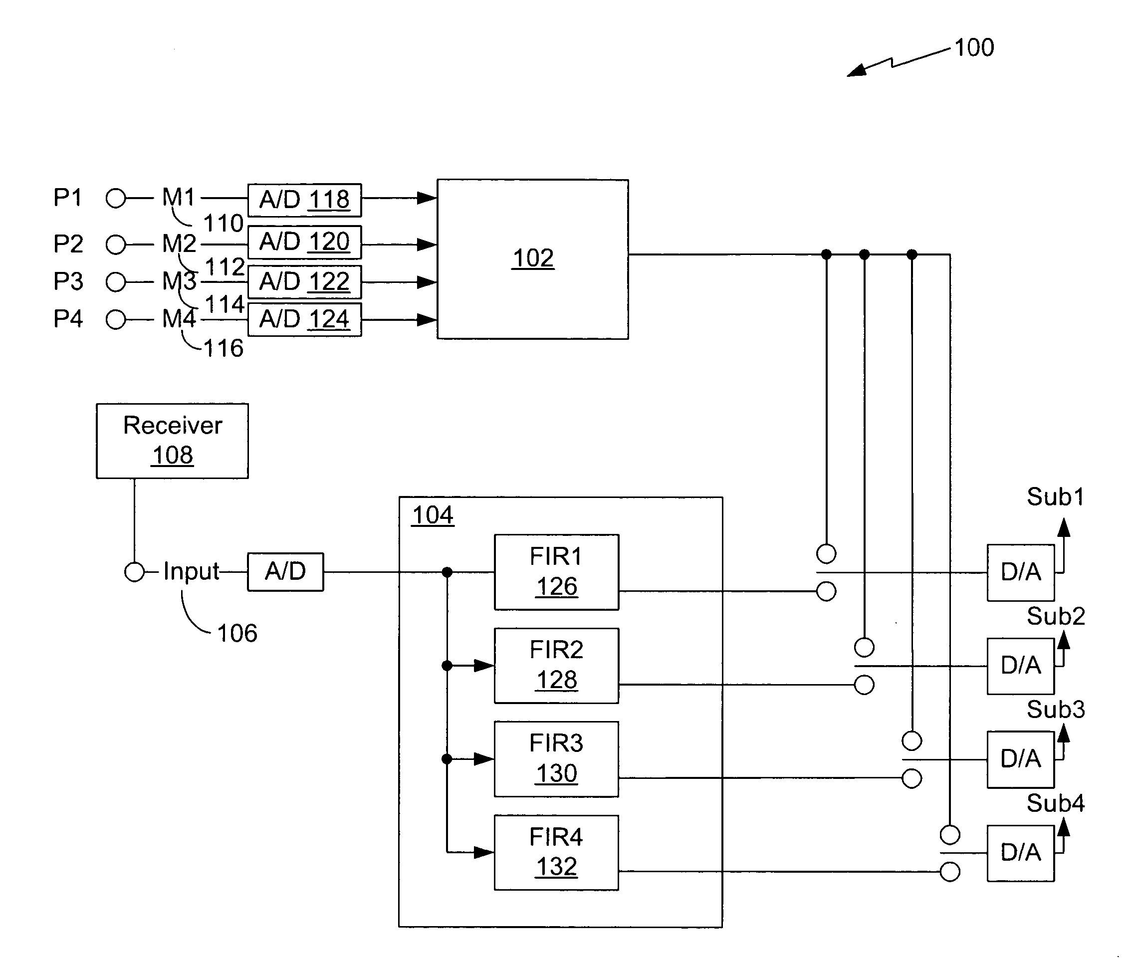
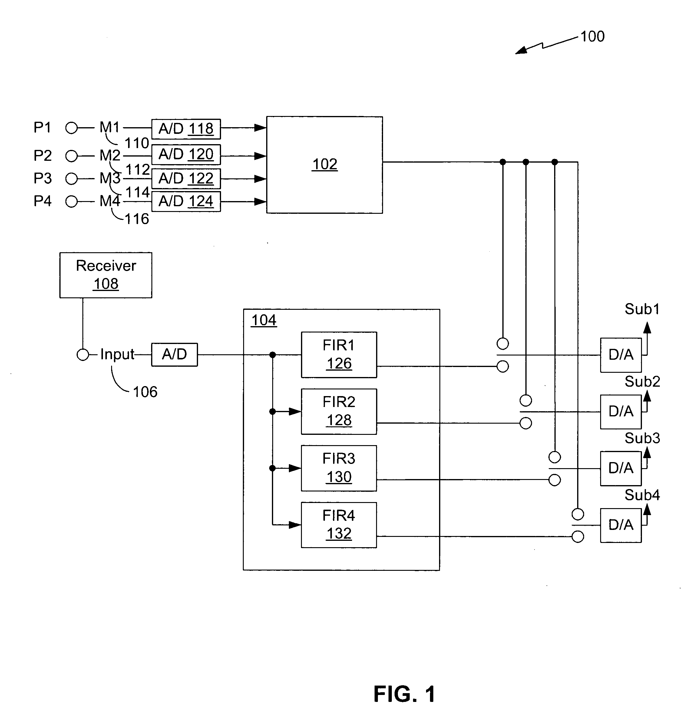
[0047]FIG. 1 is a block diagram of one example of one implementation of an equalization system 100. The equalization system 100 is able to improve bass response from one or more subwoofers positioned within a room such that the bass response within a desired listening area of the room is relatively flat across a predetermined low-frequency range. The equalization system 100 may be used to equalize frequency responses from in a variety of rooms having unique characteristics.

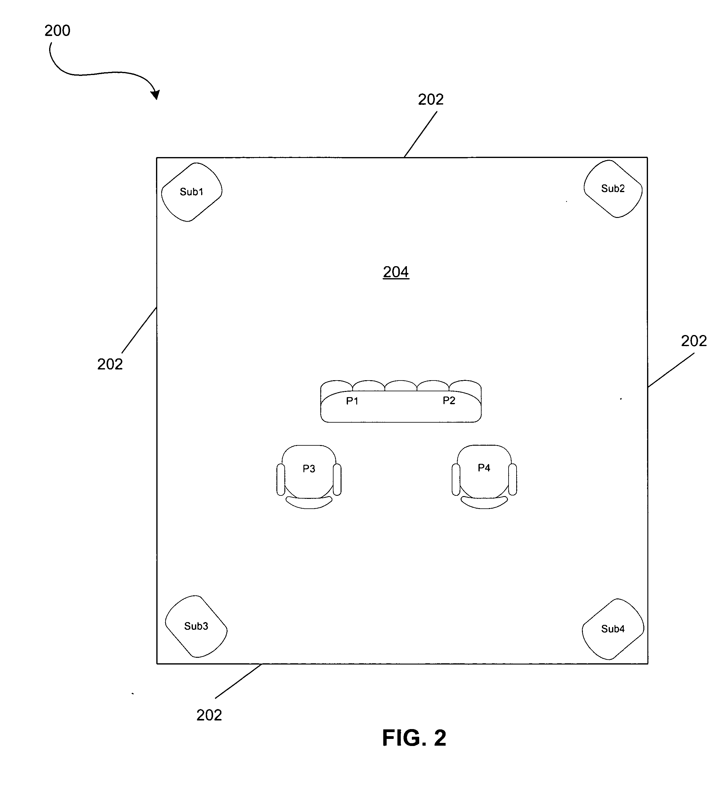
[0048]FIG. 2 illustrates one example of a listening environment in which the equalization system 100 of FIG. 1 may be employed. While the equalization system 100 may be used to equalize bass response in a variety of rooms of various types, sizes and shapes, for purposes of illustration, the equalization system 100 may be utilized in a rectangular room 200 having four walls 202, a floor 204 and a ceiling (not shown). Subwoofers Sub1, Sub2, Sub2, and Sub4 may be positioned such that one subwoofer is in each corner ...


PUM


Abstract

A frequency equalization system is provided that substantially equalizes the room frequency responses generated by at least one loudspeaker within a listening area so that the frequency responses in the listening area are substantially constant and flat within a desired frequency range with minimum signal latency. The frequency equalization system may use multiple microphones to measure the audio signals of one or more subwoofers to achieve an improved bass response that is flat across the relevant frequency range. The system employs an algorithm that is a closed-form, non-iterative, mathematical solution and features short computation time with reduced delays.

Description

CROSS REFERENCE TO RELATED APPLICATION(S) [0001] This application is a continuation-in-part of, and claims priority to, U.S. Utility patent application Ser. No. 11 / 026,773, filed on Dec. 30, 2004, titled EQUALIZATION SYSTEM TO IMPROVE THE QUALITY OF BASS SOUNDS WITHIN A LISTENING AREA, by inventors Ashish Aggarwal, Ulrich Horbach and Todd Welti, the entire application of which is incorporated by reference into this application, and claims priority to Provisional Patent Application Ser. No. 60 / 782,544, filed on Mar. 14, 2006, titled MULTI-CHANNEL, LOW LATENCY, MULTIPLE POSITION LOW FREQUENCY EQUALIZATION IN ROOMS, by inventors Ulrich Horbach, Adam Strauss and Pedro Manrique, the entire application of which is incorporated by reference into this application. BACKGROUND [0002] 1. Field of the Invention [0003] This invention relates generally to improving the quality of sound generated by one or more low-frequency loudspeakers in a listening area, and more particularly, to reduced laten...

Claims


Application Information

Patent Timeline
Patent Type & Authority Applications(United States)
IPC IPC(8): H03G5/00
CPCH03G3/32H04S7/00H03G5/005
Inventor HORBACH, ULRICHSTRAUSS, ADAMMANRIQUE, PEDRO
Owner HARMAN INT IND INC
Why Eureka
Try Eureka