
Interactive motion simulator

a motion simulator and interactive technology, applied in the field of motion simulators, can solve the problems of large number of known motion simulators which provide realistic pitch and roll motions, difficult to transport, and difficult to carry,

Inactive Publication Date: 2007-01-25
SEYMORE MICHAEL Z
View PDF14 Cites 21 Cited by
  • Summary
  • Abstract
  • Description
  • Claims
  • Application Information

AI Technical Summary

Benefits of technology

[0008] The present invention provides a motion simulator which is fully interactive for one...

Problems solved by technology

Typically, known motion simulators which provide realistic pitch and roll motions are relatively large and, as such, not readily transportable.
Smaller, relatively simple readily transportable manual devices are very limited in the motion that they provide.
Due to the use of a crank arm and cylinder, the roll arc is somewhat limited.
It does not, however, provide for inverted flight or 360 degree rolls.
While many of the prior art motion simulators provide some pitch and yaw motion, they are limited in the motion they provide and / or are relatively large, difficult to relocate, and expensive to maintain.

Method used


Image

  • Interactive motion simulator
  • Interactive motion simulator
  • Interactive motion simulator

Examples


Embodiment Construction

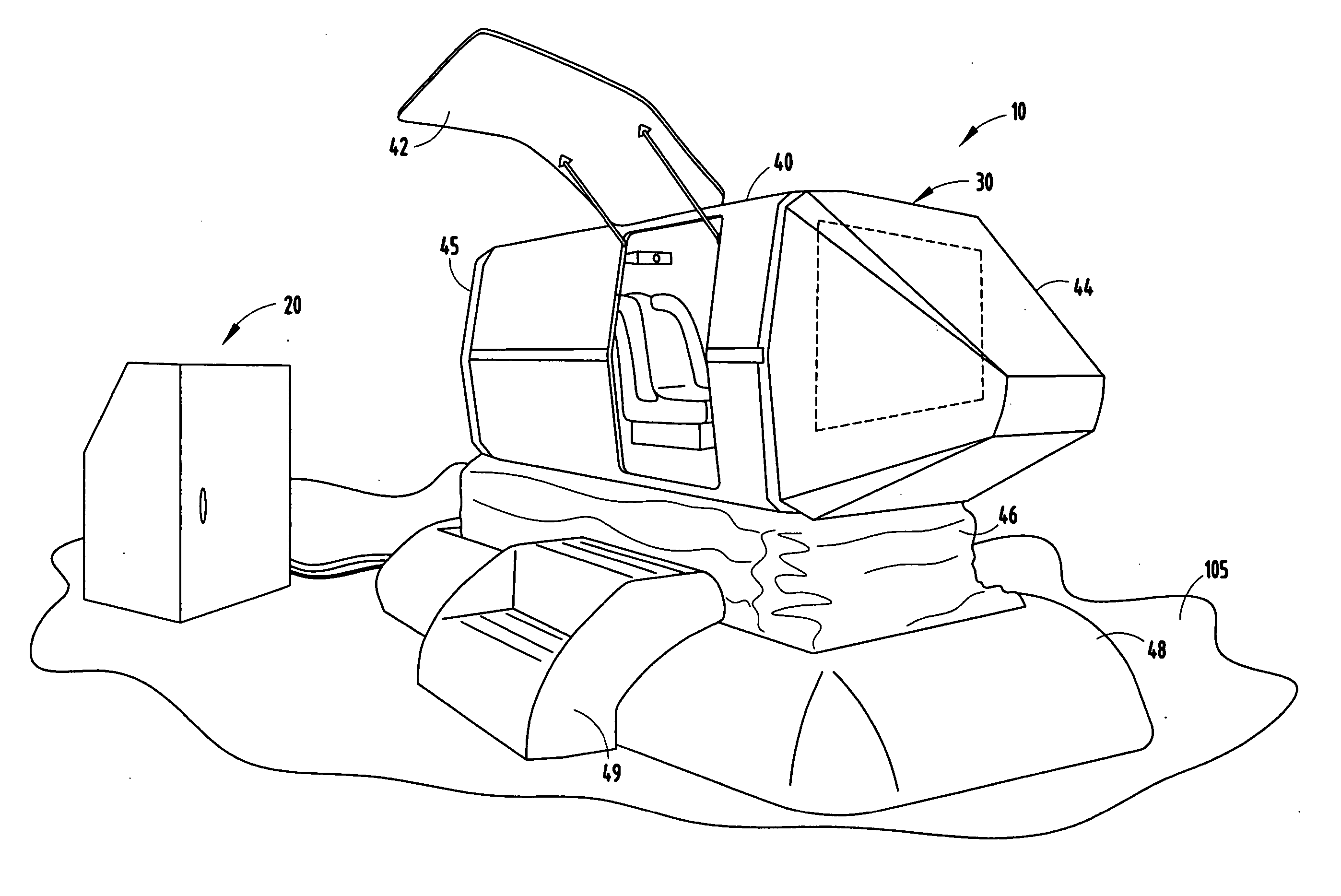
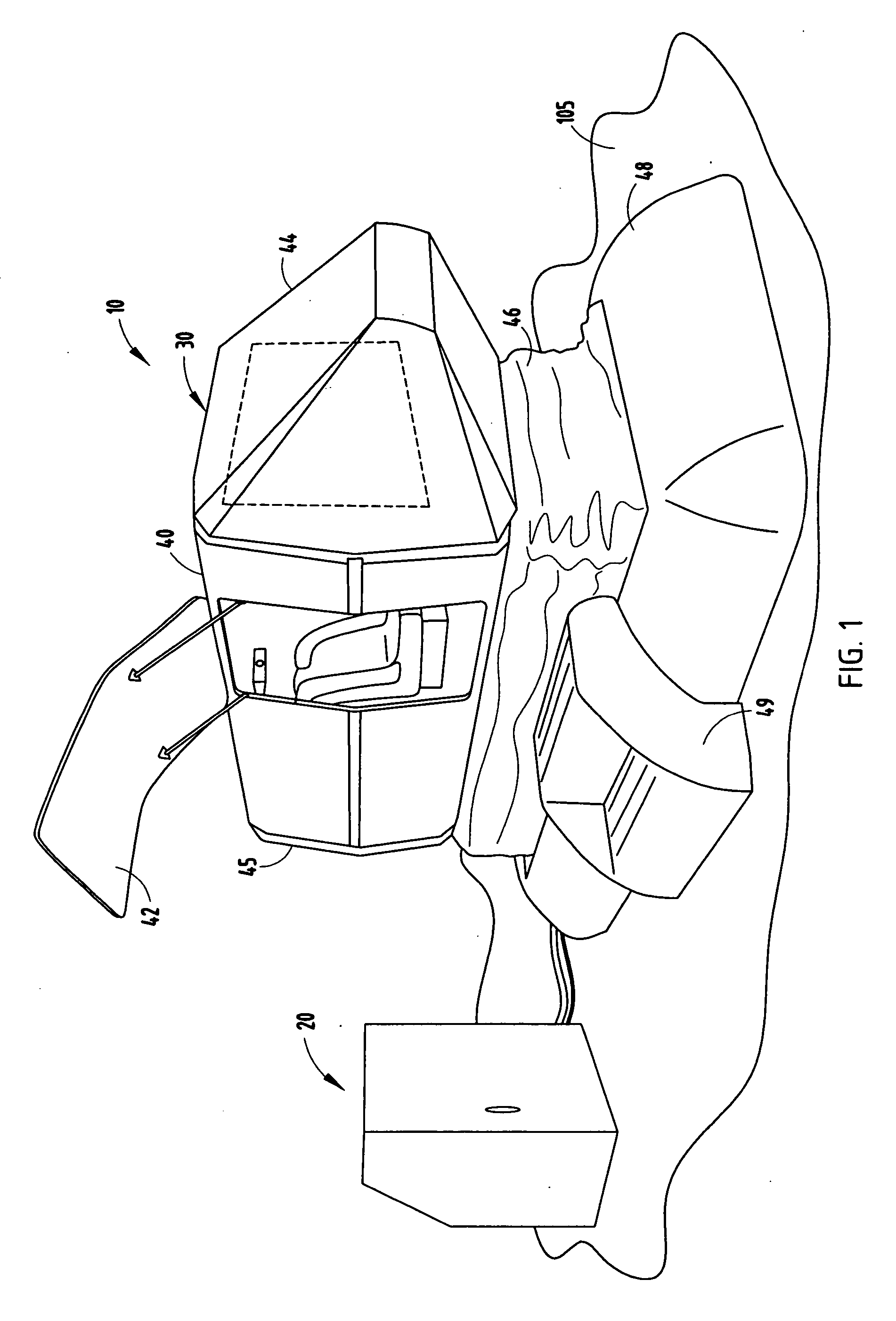
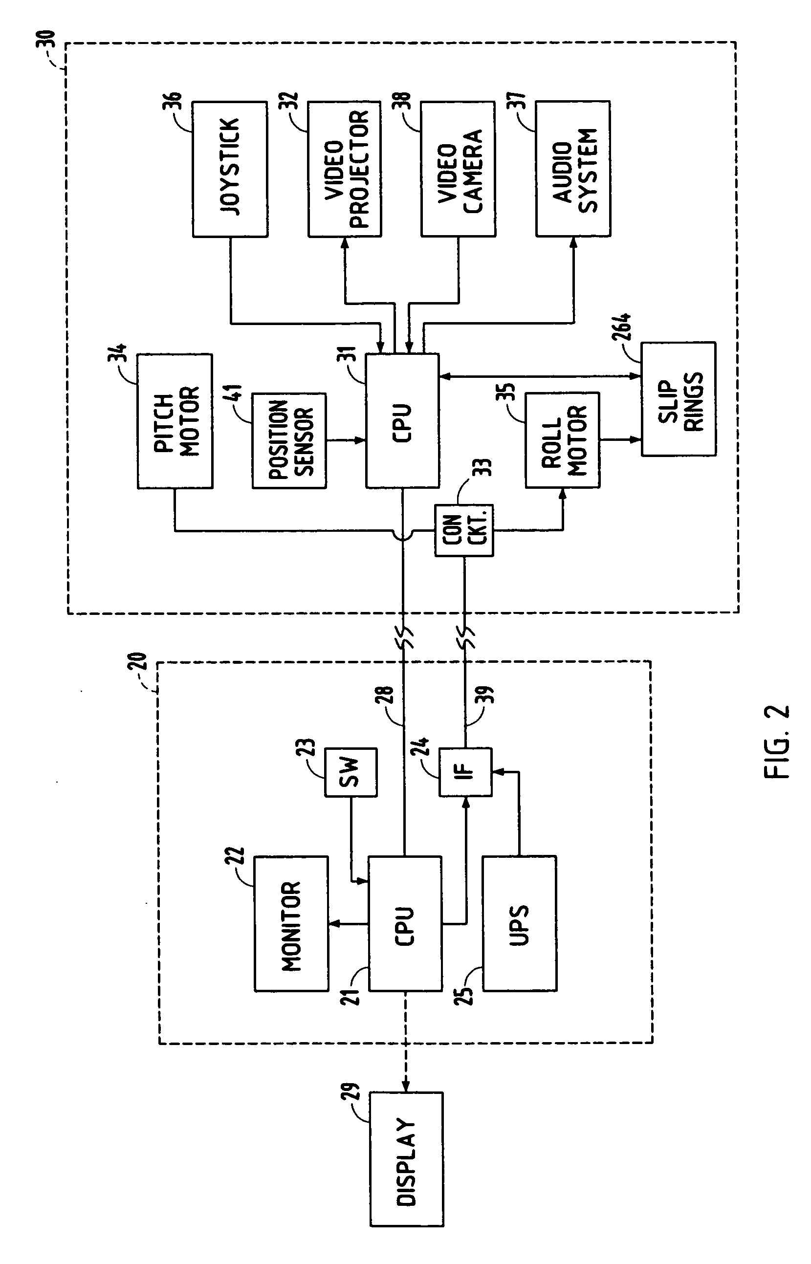
[0023]FIG. 1 shows the interactive motion simulator system 10 of the present invention, which includes a control console 20 and a motion simulator module 30. As seen in FIG. 2, the control console 20 includes a microprocessor or CPU 21, a monitor 22, operator control switches 23 coupled to the CPU, an interface circuit 24, and a universal power supply (UPS) 25. The interface circuit is coupled to a pitch motor and roll motor control circuit 33. Microprocessor 21 is coupled to a corresponding microprocessor 31 in the motion simulator module 30 through a conventional Ethernet connection 28. Microprocessor 31 includes a hard drive having graphic video programming for projecting on a video projector 32 contained within the capsule of the simulator module a topographical screen of terrain, other flying objects, and providing flight simulation motion. The simulator system also includes, as described in detail below, a pitch motor 34, a roll motor 35, and a pair of controlling joysticks 36...


PUM


Abstract

A motion simulator includes a base frame and a pitch frame pivotally mounted to the drive frame. Opposite ends of a drive coupling is coupled to ends of the pitch frame for tilting the pitch frame fore and aft. A cradle for supporting an occupant capsule is rotatably mounting to the pitch frame for rotation on an axis orthogonal to the pivot axis of the pitch frame. A roll motor is mounted to the pitch frame and coupled to one of the axles associated with the cradle for rotating the cradle and capsule. Signals from control circuits within the capsule are supplied to an operator console through a slip ring connection to allow 360 degree rotation.

Description

CROSS-REFERENCE TO RELATED APPLICATION [0001] This application claims priority under 35 U.S.C. § 119(e) on U.S. Provisional Application Ser. No. 60 / 598,980 entitled Interactive Motion Simulator, filed on Aug. 5, 2004, by Michael Z. Seymore, et al., the entire disclosure of which is incorporated herein by reference.BACKGROUND OF THE INVENTION [0002] The present invention relates to a motion simulator and, more specifically, to an interactive motion simulator. [0003] In general, a large majority of known motion simulators have been passive devices that have operated on multiple phase electrical power or employed hydraulic cylinders. Typically, known motion simulators which provide realistic pitch and roll motions are relatively large and, as such, not readily transportable. Such large motion simulators generally require disassembly and reassembly when moved from one location to another. Smaller, relatively simple readily transportable manual devices are very limited in the motion that...

Claims


Application Information

Patent Timeline
IPC IPC(8): G09B9/02
CPCG09B9/02
Inventor SEYMORE, MICHAEL Z.DUIMSTRA, DENNIS W.
Owner SEYMORE MICHAEL Z
Learn More