
System for providing and managing a laminar flow of clean air

a technology of clean air and laminar flow, applied in the field of indoor air quality control, can solve problems such as breathing conditions

Inactive Publication Date: 2007-01-25
KENNEDY MICHAEL ANTHONY
View PDF9 Cites 48 Cited by
  • Summary
  • Abstract
  • Description
  • Claims
  • Application Information

AI Technical Summary

Problems solved by technology

If conditions are not found to be in compliance with those upon which the area and process was validated originally, then it is said that breached conditions exist.

Method used


Image

  • System for providing and managing a laminar flow of clean air
  • System for providing and managing a laminar flow of clean air
  • System for providing and managing a laminar flow of clean air

Examples


Embodiment Construction

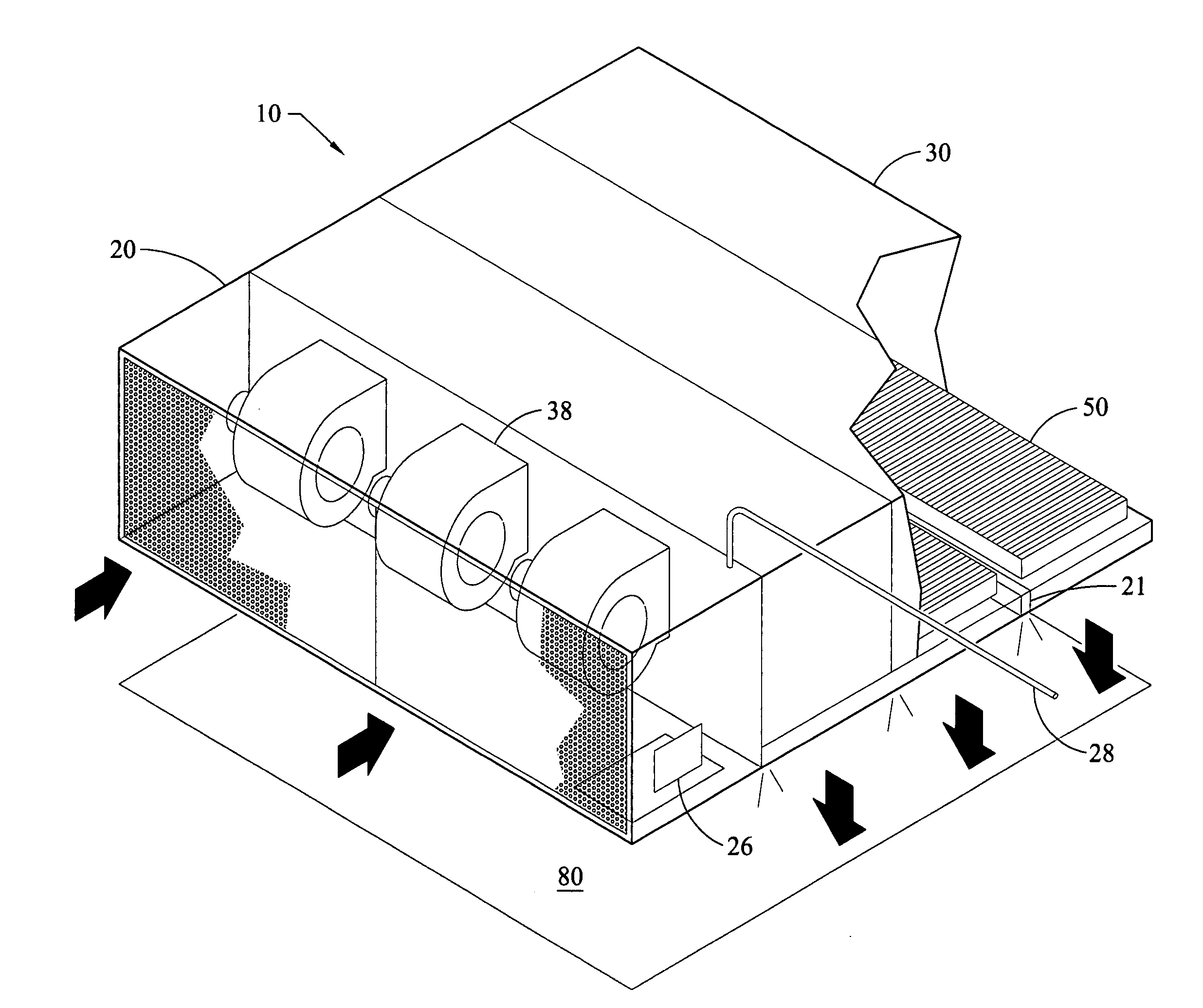
[0028] For the purposes of promoting an understanding of the principles of the invention and presenting its currently understood best mode of operation, reference will now be made to the embodiments illustrated in the drawings and specific language will be used to describe the same. It will nevertheless be understood that no limitation of the scope of the invention is thereby intended, with such alterations and further modifications in the illustrated device and such further applications of the principles of the invention as illustrated therein being contemplated as would normally occur to one skilled in the art to which the invention relates.

[0029] With reference to the figures, one embodiment of Applicant's laminar air system 10, called the Clean Air Continuity Management (CACM) system will be described. The disclosure of the CACM system is not intended to be limiting with respect to the potential application of other aspects of Applicant's invention.

[0030] In the preferred embo...


PUM


Abstract

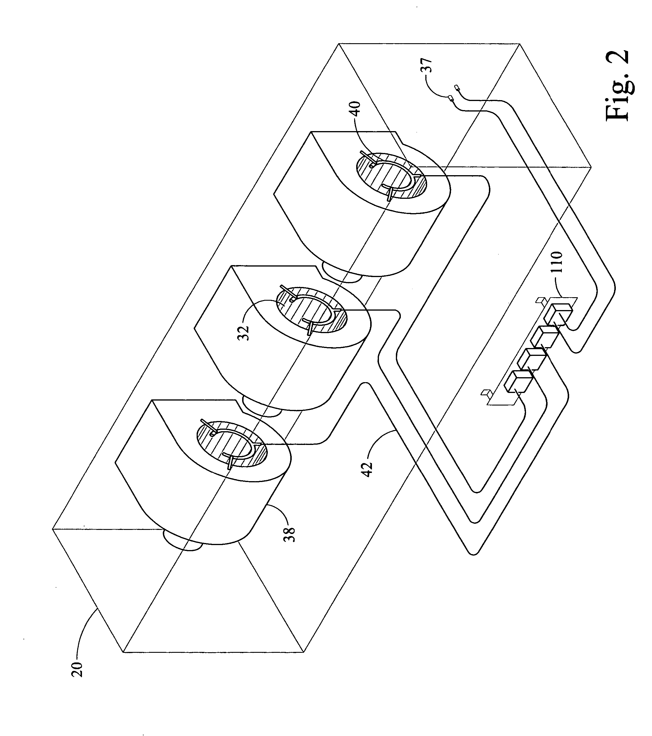
A system for providing and managing a laminar flow of filtered air for a clean room workspace has a blower for blowing air through a filter and over the work area. The velocity of air flowing through the filter is automatically controlled by a feedback loop wherein sensors enable the system to learn of a drop in flow, or even a flow rate that strays above a set point, and to then take action to change settings of the variable frequency drive which, in turn, vary the current to the motors causing a change in blower speed. The system's programmable logic control also provides for automatic recording and storing of data relating to the operating characteristics of the system, including the date and time that the operating characteristics were recorded. The recording may be done in a manner so as not to be editable by the system operator, which makes such record compliant with federal regulations.

Description

REFERENCE TO RELATED APPLICATIONS [0001] This application claims the benefit of provisional application No. 60 / 691,075, filed Jun. 16, 2005, which is incorporated herein by reference.TECHNICAL FIELD OF THE INVENTION [0002] The invention generally relates to in-door air quality control, and more particularly to a system for providing and managing a laminar flow of filtered air for a clean room workspace. BACKGROUND OF THE INVENTION [0003] HEPA or ULPA filtered laminar flow is an aseptic column of air pushing either vertically or horizontally with piston-like precision across the workplace, displacing room-generated particles and process-generated particles and moving them into the air filters for interception. These conditions remain in place workday after workday. [0004] A pharmaceutical clean room may be either a turbulent flow or a laminar flow clean room. In the case of turbulent flow, the particle count is kept at or below acceptance criteria by means of dilution with a known vo...

Claims


Application Information

Patent Timeline
Patent Type & Authority Applications(United States)
IPC IPC(8): B01L1/04
CPCF24F3/161Y02B30/746F24F2011/0042F24F11/0079F24F2110/40F24F11/77Y02B30/70F24F3/167
Inventor KENNEDY, MICHAEL ANTHONY
Owner KENNEDY MICHAEL ANTHONY
Learn More