Golf putter with removeable inserts for altering the center of gravity of the putter

a technology of inserts and golf balls, which is applied in the field of golf clubs, can solve the problems of not being able to allow reflection surfaces, and achieve the effect of removing the insert quickly and easily, accurately and accurately striking the golf ball

Inactive Publication Date: 2007-01-25
OPITX GOLF COMPANY
View PDF43 Cites 17 Cited by
  • Summary
  • Abstract
  • Description
  • Claims
  • Application Information

AI Technical Summary

Benefits of technology

[0007] The device of the present invention comprises a golf club, and more specifically a putter, that includes a plurality of physical and visual aids for assisting the golfer to more consistently assume a good head and body position for putting and to strike a golf ball more correctly and accurately. The club includes a putter head mounted on a shaft. The putter head is selectively engaged with any one of a plurality of detachable flanges. The flanges are all of different lengths, weights and shapes and are designed to change the center of gravity of the putter head when they are individually engaged therewith. The change in the center of gravity aids in helping the golfer to correctly and accurately strike the golf ball. Each of the detachable flanges includes a first reflective surface and a second non-reflective surface and all are also provided with a second linear marking that is alignable with a first linear marking on the putter head. The reflective surface is used during practice sessions to aid the golfer in correctly positioning his head by aligning his eyes along the second linear marker and aligning the first and second linear markers with a remote hole. The golfer uses this reflective surface to train himself to hold his head correctly. The reflective surface is not allowed, however, in United States Golf Association (USGA) sanctioned games. In order to bring the putter into compliance with USGA regulations, the selected one of the flanges is quickly and easily removed from the putter head, flipped over and reinserted into the putter head so that the non-reflective surface is facing upwardly. The putter of the present invention is also provided with spaced apart weight ports into which small weights may be inserted so as to balance the putter head and help the golfer hold the putter head in a correct orientation for successful putting.

Problems solved by technology

The reflective surface is not allowed, however, in United States Golf Association (USGA) sanctioned games.

Method used


Image

  • Golf putter with removeable inserts for altering the center of gravity of the putter
  • Golf putter with removeable inserts for altering the center of gravity of the putter
  • Golf putter with removeable inserts for altering the center of gravity of the putter

Examples


fourth embodiment

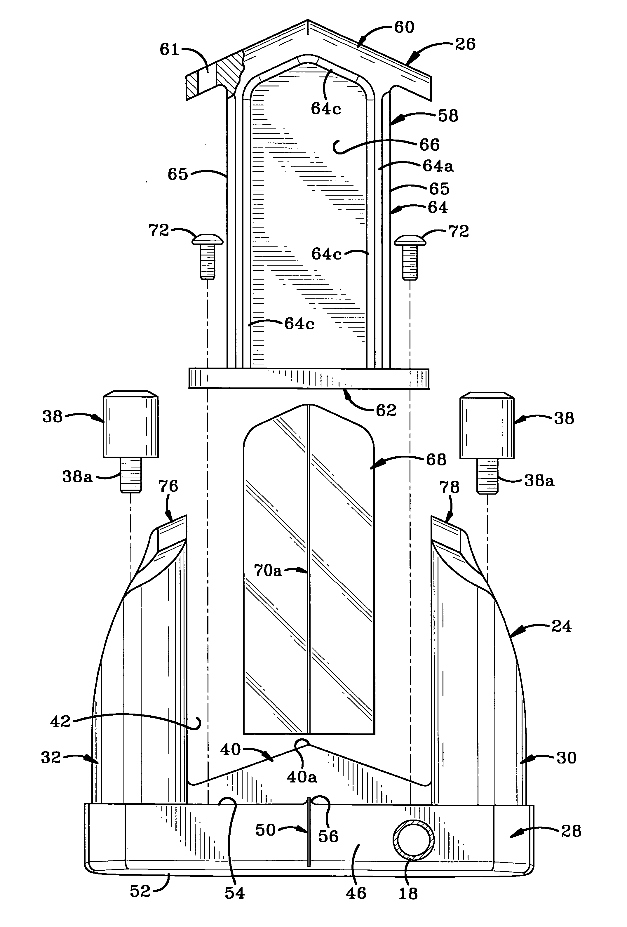
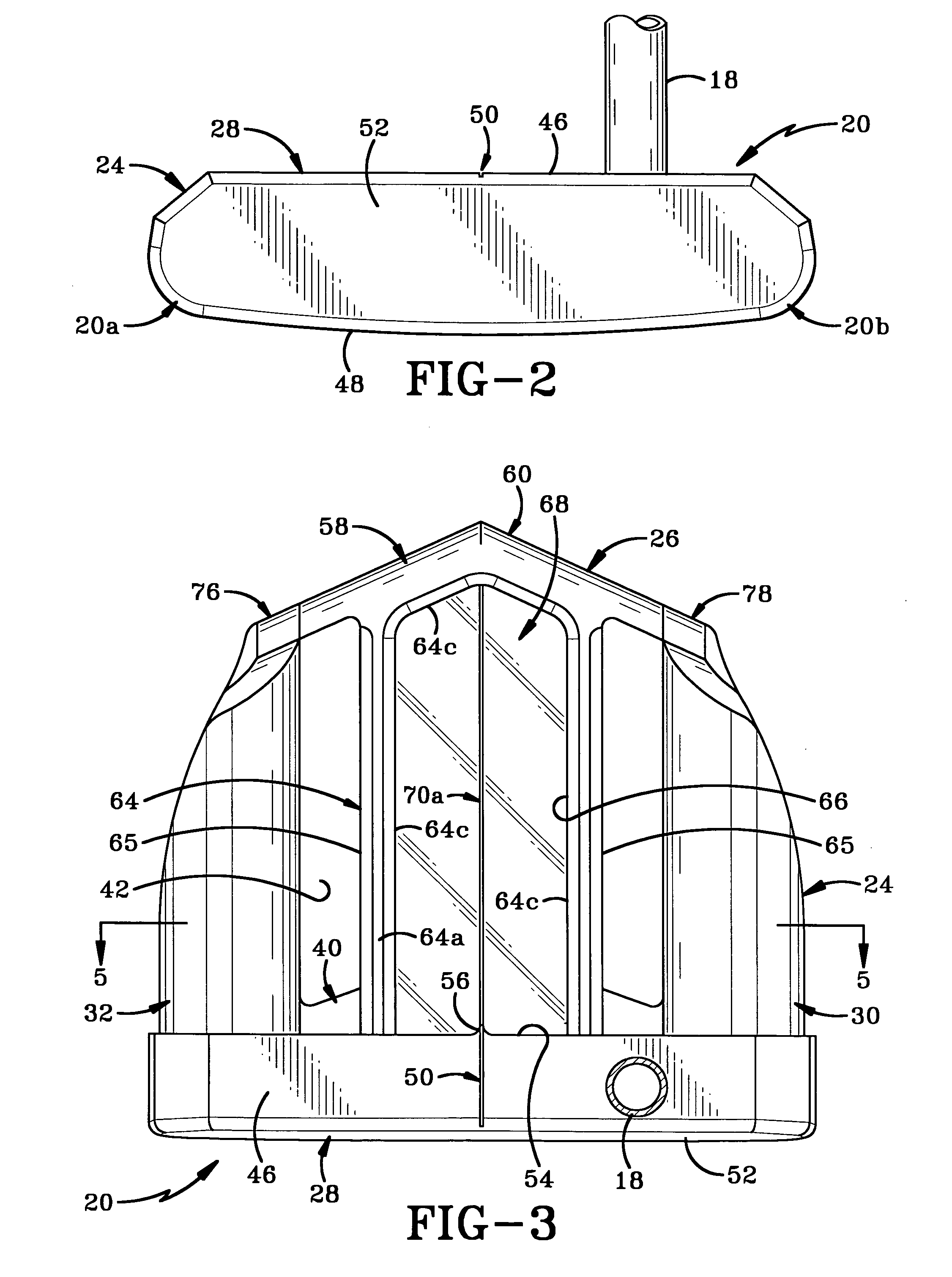
[0041]FIG. 16 illustrates a putter head 20 that is engaged with a removeable flange, which flange is generally indicated at 326. Flange 326 is secured to rear surface 54 of front wall 28 of base 24. However, it will be understood that flange 326 could also be secured to one or both legs 30, 32 or to a combination of the legs 30, 32 and rear face 54 of front wall 28. Flange 326 is substantially identical to flange 26 except that flange 326 is at least one of a reduced size and different weight to flange 26. When flange 326 is engaged with base 24, the V-shaped back end 360 of flange 326 terminates a distance inwardly from terminal ends 76, 78 of base 24. Flange 326 includes a mirrored plate 368 on an upper surface thereof and is non-reflective on a lower surface (not shown). As with previous embodiments, flange 326 is provided with a second linear marking 370a that serves as an extension of first linear marking 50 on front wall 28. Flange 326 may be either lighter or heavier than fla...

fifth embodiment

[0042]FIG. 17 illustrates flange, being the flange indicated generally at 426. Flange 426 is substantially identical to the flange 226 shown in FIG. 8, except flange 426 is again of a diminished size and different weight to flange 226. Flange 426 includes a peripheral wall 462 that is not substantially continuous with terminal ends 76, 78 of legs 32, 30. Peripheral wall 462 terminates a distance inwardly of terminal ends 76, 78 of base 24. Flange 426 includes an upper surface having a mirrored insert 468 therein and a lower surface (not shown) that is non-reflective. Mirrored insert 468 also includes a second linear marking 470a that aligns with the first linear marking 50 on base 24. As with previous embodiments, flange 426 is easily removed by unscrewing the Allen screws (not shown) that secure it to the base 24 and this makes it easy for the golfer to switch between various length, weight and shape flanges and to thereby change the putting characteristics of his putter. It would ...


PUM


Abstract

A golf putter including a plurality of physical and visual aids for assisting the golfer to more consistently assume a good head and body position and to better putt a golf ball toward a remote hole. The putter head is engaged with one of a plurality of detachable flanges. The flanges all have different lengths, weights and shapes and are selectively engaged with the putter head to change its center of gravity and thereby change the characteristics of the putter. The golfer selectively engages the appropriate one of the plurality of flanges to give the putter head the type of characteristics that best suit his personal putting abilities and deficiencies and is thereby aided in correctly and accurately striking the golf ball. Each of the detachable flanges is provided with a first reflective surface and a second non-reflective surface. The reflective surfaces are all provided with a second linear marking thereon. The second linear marker is alignable with a first linear marking on the putter head and with the remote hole toward which the ball is to be putted. The reflective surface is used during practice sessions to aid the golfer in correctly positioning his head and body. The selected flange is removed and rotated during USGA sanctioned golf games to present the non-reflective surface on the upper side of the club. The different flanges are quickly and easily engaged with the putter head, so the golfer may change the nature of the putter for each hole they encounter on the golf course.

Description

CROSS-REFERENCE TO RELATED APPLICATIONS [0001] This application is a continuation-in-part of U.S. patent application Ser. No. 11 / 337,428 filed Jan. 23, 2006, which is a standard utility application that claims priority from U.S. Provisional Application No. 60 / 702,131, filed Jul. 25, 2005, the entire specifications of which are incorporated herein by reference.BACKGROUND OF THE INVENTION [0002] 1. Technical Field [0003] This invention generally relates to golf clubs. More particularly, the invention relates to a golf putter. Specifically, the invention relates to a golf putter that includes a variety of visual aids useful for training the golfer to correctly position their head and body so as to more consistently putt well. [0004] 2. Background Information [0005] Golfers are always trying to improve their game and, consequently, they are always seeking out aids, teaching tools, videos and programs that will assist them in improving their game and achieving their potential as a golfer...

Claims


Application Information

Patent Timeline
Patent Type & Authority Applications(United States)
IPC IPC(8): A63B69/36A63B53/06A63B53/00
CPCA63B24/0003A63B53/0487A63B53/065A63B2225/12A63B2053/0441A63B2053/0491A63B2069/3682A63B69/3685A63B60/02A63B53/0441A63B69/3682
Inventor HAACK, SCOTT G.
Owner OPITX GOLF COMPANY
Why Eureka
Try Eureka