
Portable device having biosignal-measuring instrument

a biosignal and measuring instrument technology, applied in the field of portable devices having biosignal measuring instruments, can solve the problems of inconvenience for users, inconvenient carrying, and frequent errors of biosignal measurement, and achieve the effect of reducing the error of pulse waveform and more accurate biosignal information

Active Publication Date: 2007-01-25
SAMSUNG ELECTRONICS CO LTD
View PDF14 Cites 21 Cited by
  • Summary
  • Abstract
  • Description
  • Claims
  • Application Information

AI Technical Summary

Benefits of technology

The present invention is a portable device that can measure a user's electrocardiogram and pulse waveform simultaneously using a special sensor. This device can detect characteristic points of the pulse waveform by referring to the electrocardiogram waveform, which helps to reduce errors caused by external factors like hand shaking. As a result, the device can provide more accurate biosignal information.

Problems solved by technology

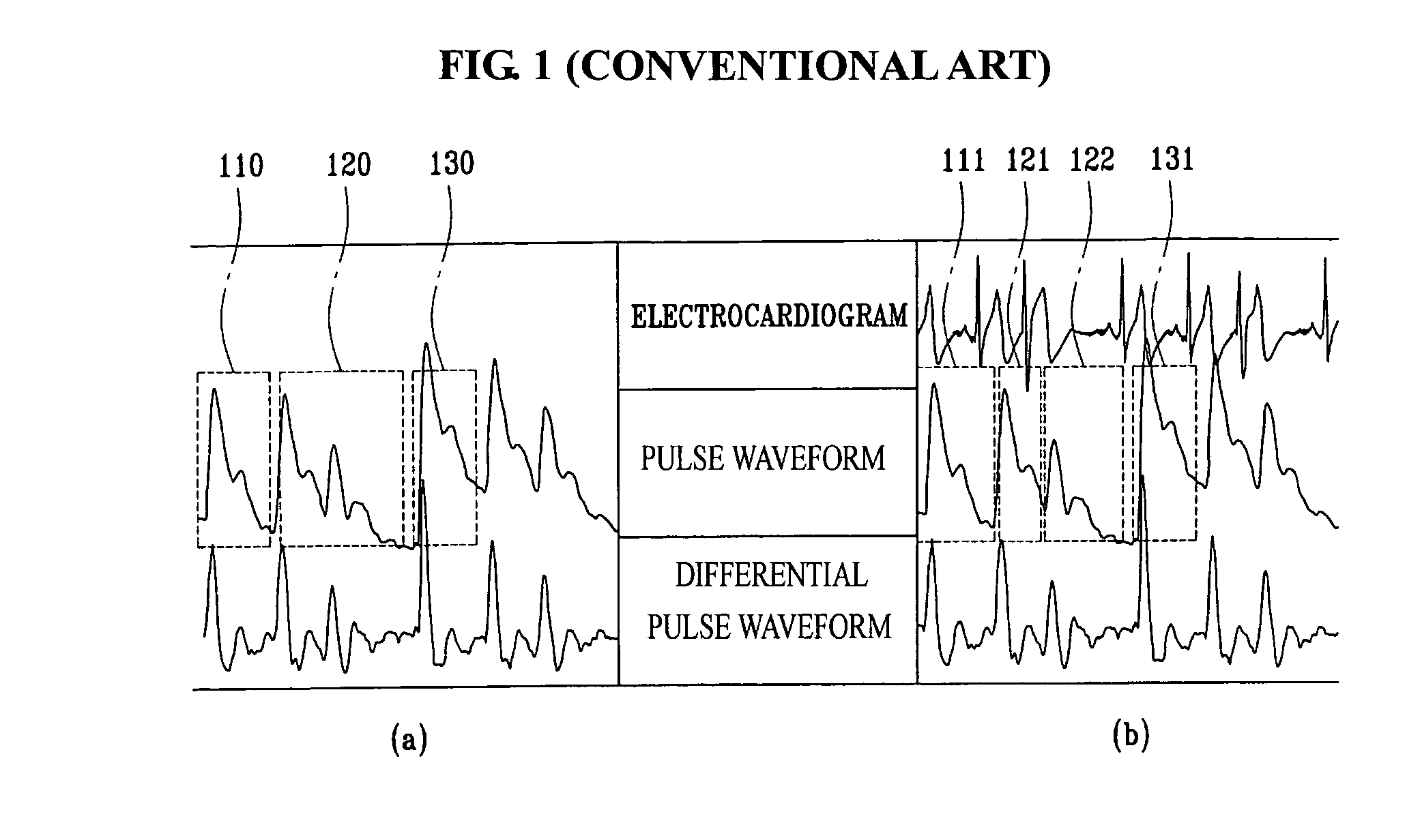
The technical problem addressed in this patent text is the need for a portable device that can simultaneously measure a user's pulse and electrocardiogram signals, to obtain more precise biometric information. The current methods for measuring pulse waves are inconvenient and may result in errors when measuring the pulse waveform.

Method used


Image

  • Portable device having biosignal-measuring instrument
  • Portable device having biosignal-measuring instrument
  • Portable device having biosignal-measuring instrument

Examples


first embodiment

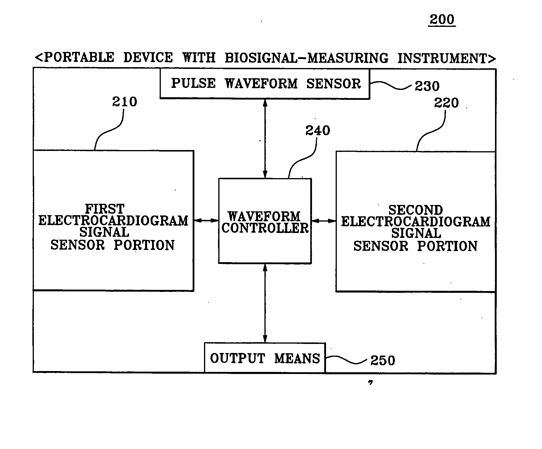
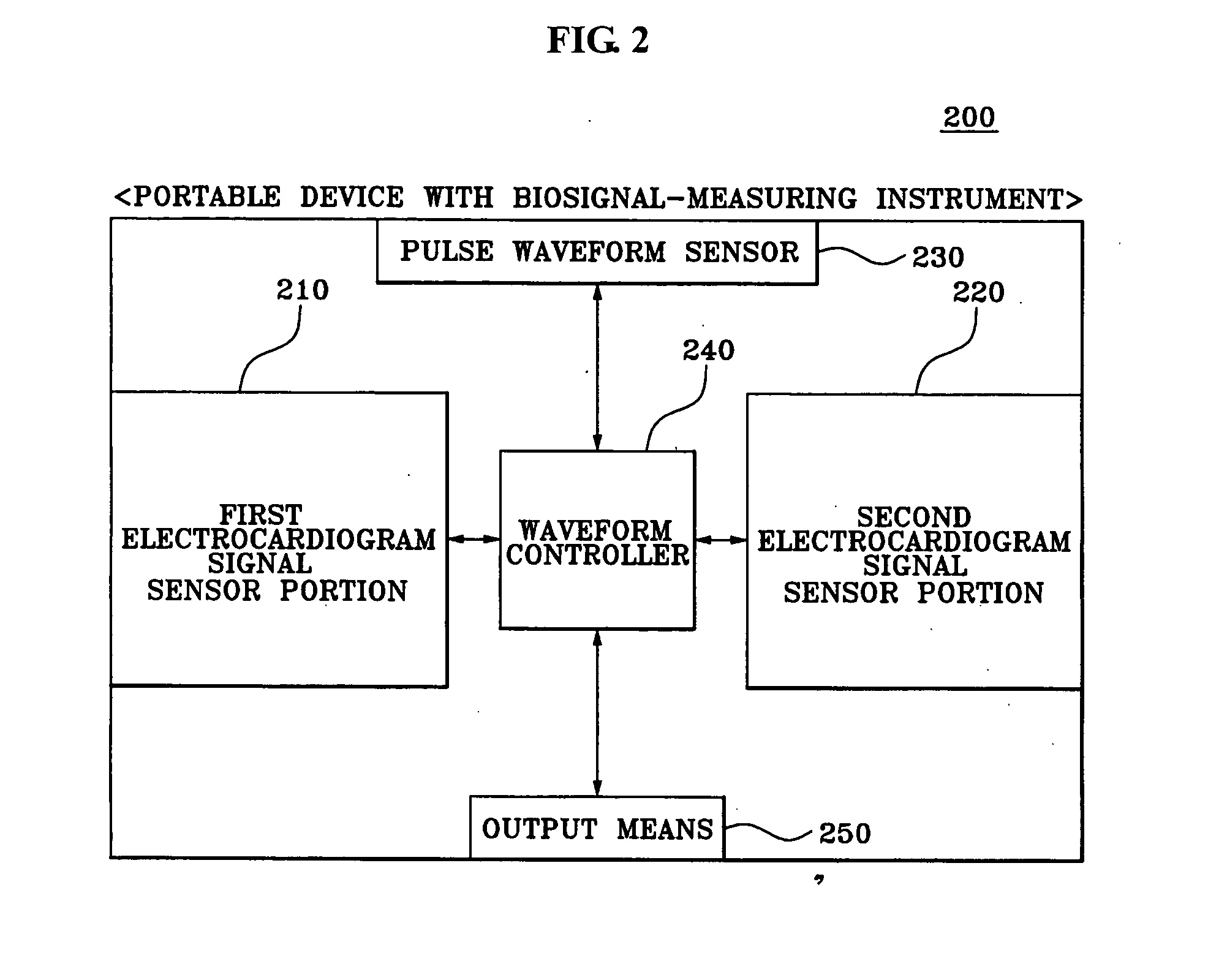
[0040]FIG. 2 is a block diagram illustrating a configuration of a biosignal measuring portable device according to the present invention.

[0041] A portable device 200 having a biosignal measuring instrument according to the first embodiment of the present invention includes a first electrocardiogram signal sensor portion 210, a second electrocardiogram signal sensor portion 220, a pulse waveform sensor 230, a waveform controller 240, and an output means 250.

[0042] At least one first electrocardiogram signal sensor portion 210 is provided on a first surface of the portable device 200 that a user can make contact with a first hand, and measures a first electrocardiogram signal of the user from a first hand of the user who has grasped the portable device 200. For example, the first electrocardiogram signal sensor that the user makes contact with as the user grasps the portable device 200 may be provided on the side of the portable device 200.

[0043] At least one second electrocardiogra...

second embodiment

[0069]FIG. 6 is a block diagram illustrating a configuration of a portable device having a biosignal measuring instrument according to the present invention.

[0070] A portable device 600 having a biosignal measuring instrument according to the second embodiment of the present invention may be used in traditional oriental medicine in taking the negative and positive pulse by measuring a carotid pulse waveform from the neck of a user and measuring a radial arterial pulse waveform from the wrist of the user.

[0071] The portable device 600 having the biosignal measuring instrument according to the second embodiment of the present invention includes a first sensor portion 610, a second sensor portion 620, a waveform controller 630, and an output means 640.

[0072] The first sensor portion 610 includes a first pulse waveform sensor 611 which is connected to the portable device 600 via a predetermined cable to make contact with the neck of a user, thereby converting a carotid pulse waveform ...


PUM


Abstract

A portable device having a biosignal measuring instrument includes: at least one first electrocardiogram signal sensor portion on a first surface of the portable device that contacts a first hand of a user, to measure a first electrocardiogram signal of the user; at least one second electrocardiogram signal sensor portion on a second surface of the portable device that contacts a wrist of a second hand of the user, to measure a second electrocardiogram signal from the wrist; a pulse waveform sensor on the second surface and in parallel with the second electrocardiogram signal sensor portion, to sense a pulse waveform from the wrist; a waveform controller generating an electrocardiogram waveform of the user from the measured first electrocardiogram signal and second electrocardiogram signal, generating a pulse waveform of the user from the sensed pulse waveform, and detecting at least one characteristic point of the pulse waveform by referring to the electrocardiogram waveform; and an output portion providing a result of the pulse wave analysis based on the at least one detected characteristic point of the user.

Description


Claims


Application Information

Patent Timeline
Owner SAMSUNG ELECTRONICS CO LTD
Learn More