
Card tray

a card tray and card slot technology, applied in the direction of electrical apparatus casings/cabinets/drawers, coupling device connections, instruments, etc., can solve the problem of not being able to and receive memory cards of different types

Inactive Publication Date: 2007-02-01
SONY CORP +1
View PDF10 Cites 12 Cited by
  • Summary
  • Abstract
  • Description
  • Claims
  • Application Information

AI Technical Summary

Benefits of technology

[0016] As a matter of course, memory card adaptors to be used for such downsized memory cards have reduced external dimensions.
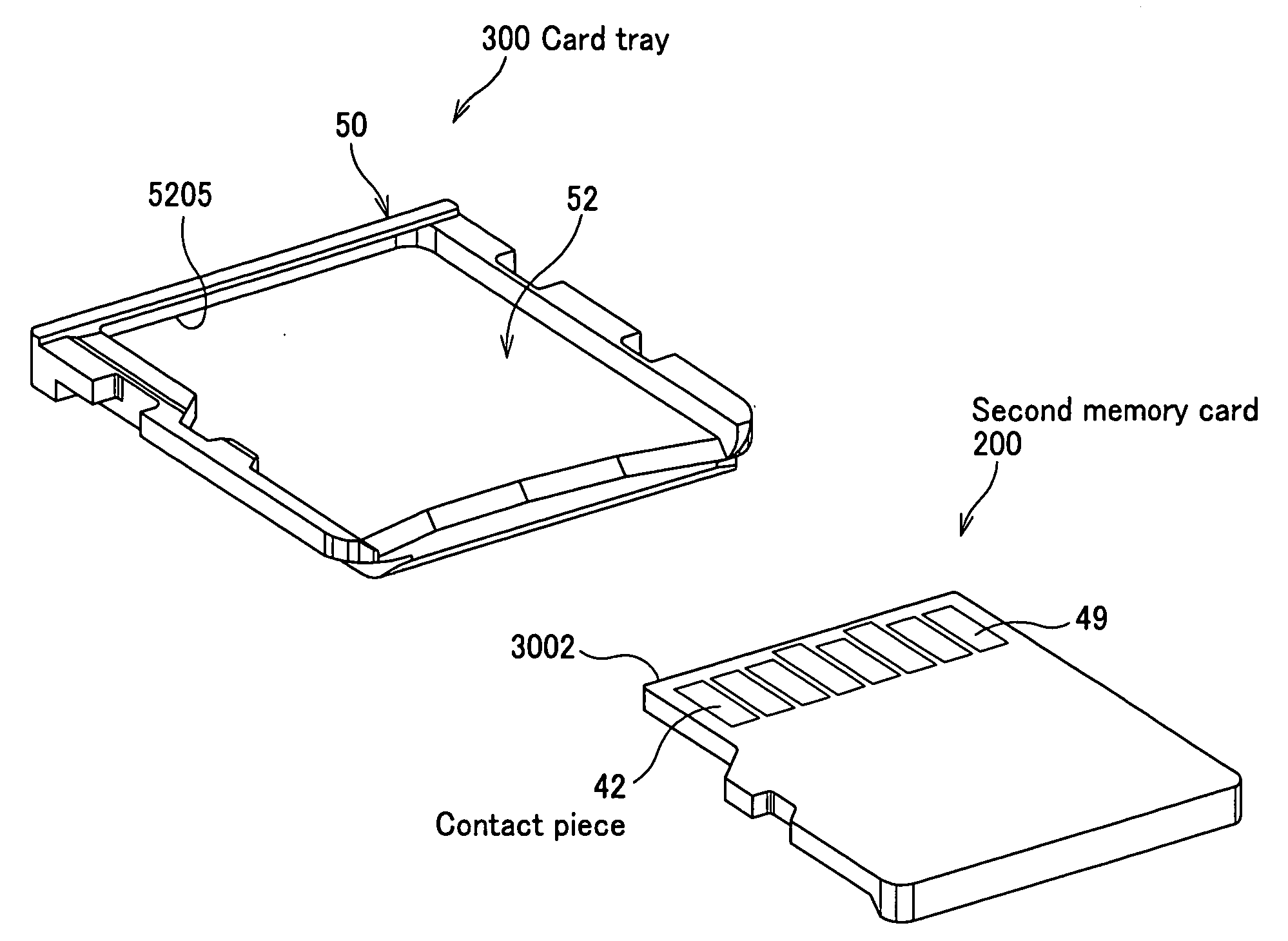
[0021] Therefore, unlike card adaptors used in the past, the card tray does not have to have any adaptor side contact pieces and conductor members and hence it is possible to make the external dimensions of the card tray agree with those of the downsized first memory card so that the second memory card can be mounted in the card slot for receiving the first memory card by mounting it to a card tray and forming a memory-card-mounted body.

Problems solved by technology

Therefore, any single card slot for receiving a memory card is not able to receive memory cards of different types.

Method used


Image

  • Card tray
  • Card tray
  • Card tray

Examples


first embodiment

[0038] Now, the first embodiment of the present invention will be described in detail by referring to the accompanying drawings.

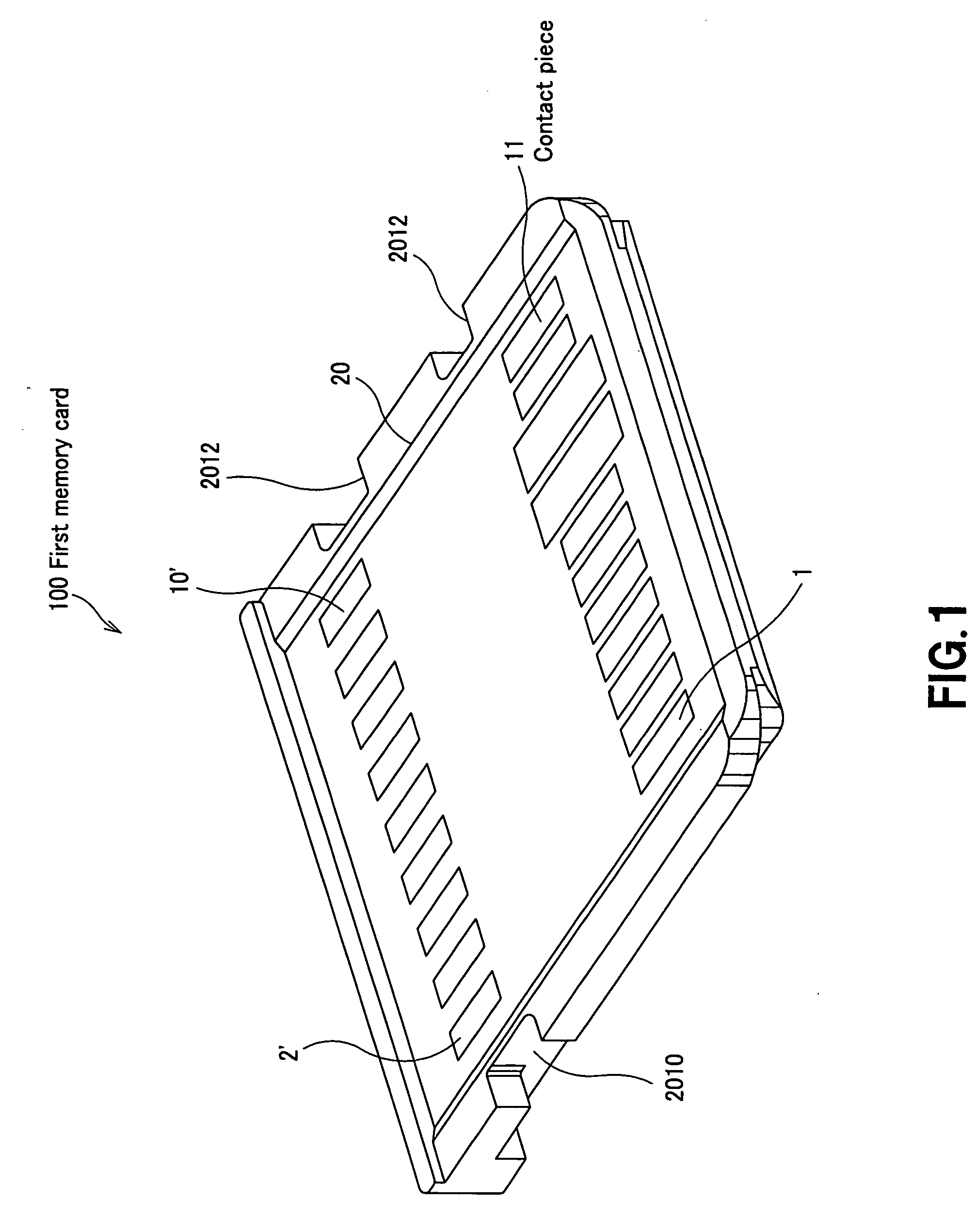
[0039]FIG. 1 is a schematic perspective view of a first memory card 100.

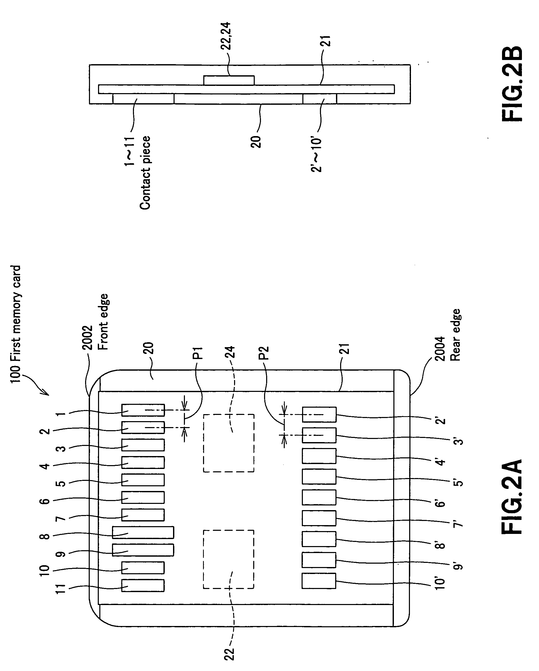
[0040]FIG. 2A is a schematic plan view of the first memory card 100, and FIG. 2B is a schematic cross sectional view of the first memory card 100.

[0041]FIG. 3A is a chart illustrating the correspondence between the contact pieces of the first memory card 100 and signal names.

[0042] In the following description, the side of each of the first memory card 100 and second memory card 200 by which the card is inserted into a card slot is referred to as front edge whereas the side of each of first memory card 100 and second memory card 200 by which the card is taken out from the card slot is referred to as rear edge.

[0043] The side of each of the first memory card 100 and second memory card 200 and card tray 300 that is found at the right side as viewed from the rear edge is referred to a...


PUM


Abstract

A card tray to be mounted to a memory card can make the memory card mountable in a card slot for memory cards conforming to standards different from those to which the memory card conforms. The card tray has a main body and a recessed mount section. The recessed mount section is formed such that the holder of a second memory card can be mounted to one of the major surfaces of the main body. A memory-card-mounted body is produced when the second memory card is mounted to the recessed mount section. The card tray is configured such that, when the first memory card is placed on the memory-card-mounted body with the left and right edges thereof aligned with each other, the contact pieces of the first memory card and the contact pieces of the second memory card have longitudinally overlapping parts and transversally overlapping parts as viewed from above.

Description

CROSS REFERENCES TO RELATED APPLICATIONS [0001] The present invention contains subject matter related to Japanese Patent Application JP 2005-215965 filed in the Japanese Patent Office on Jul. 26, 2005, the entire contents of which being incorporated herein by reference. BACKGROUND OF THE INVENTION [0002] 1. Field of the Invention [0003] The present invention relates to a card tray to which a memory card is mounted. [0004] 2. Description of the Related Art [0005] Memory cards including a writable flash memory are being marketed so as to be used for writing data in and reading data from the flash memory. [0006] Such a memory card is typically mounted in the card slot (connector) of an external apparatus such as personal computer or portable telephone set so as to be used for writing data in and reading data from the flash memory of the memory card. [0007] Known memory cards include Memory Sticks (Registered Trademark, available from Sony Corporation), Multi Media Cards (MMC: Registere...

Claims


Application Information

Patent Timeline
IPC IPC(8): G06K19/06G06K7/00G06K17/00G06K19/077H01R31/06
CPCG06K19/077G06K19/07739Y10S439/945G06K19/00G06K19/07
Inventor AOKI, YOSHITAKATSUTSUI, KEIICHINISHIZAWA, HIROTAKATOTSUKA, TAKASHI
Owner SONY CORP
Learn More