Droplet deposition position error measurement method, droplet deposition position error adjustment method, droplet ejection control method, and image forming apparatus

Inactive Publication Date: 2007-02-01
FUJIFILM CORP
View PDF2 Cites 30 Cited by
  • Summary
  • Abstract
  • Description
  • Claims
  • Application Information

AI Technical Summary

Benefits of technology

[0048] According to the present invention, a first error component caused by an error in the relative position between the liquid ejection head and the recording medium, and a second error component caused by an error in the ejection direction of each of the liquid droplet

Problems solved by technology

The error measured in this way includes a first error component caused by an error in the relative position of the head and the recording med

Method used


Image

  • Droplet deposition position error measurement method, droplet deposition position error adjustment method, droplet ejection control method, and image forming apparatus
  • Droplet deposition position error measurement method, droplet deposition position error adjustment method, droplet ejection control method, and image forming apparatus
  • Droplet deposition position error measurement method, droplet deposition position error adjustment method, droplet ejection control method, and image forming apparatus

Examples


Example

Second Embodiment

[0180] Next, a second embodiment of the present invention is described below.

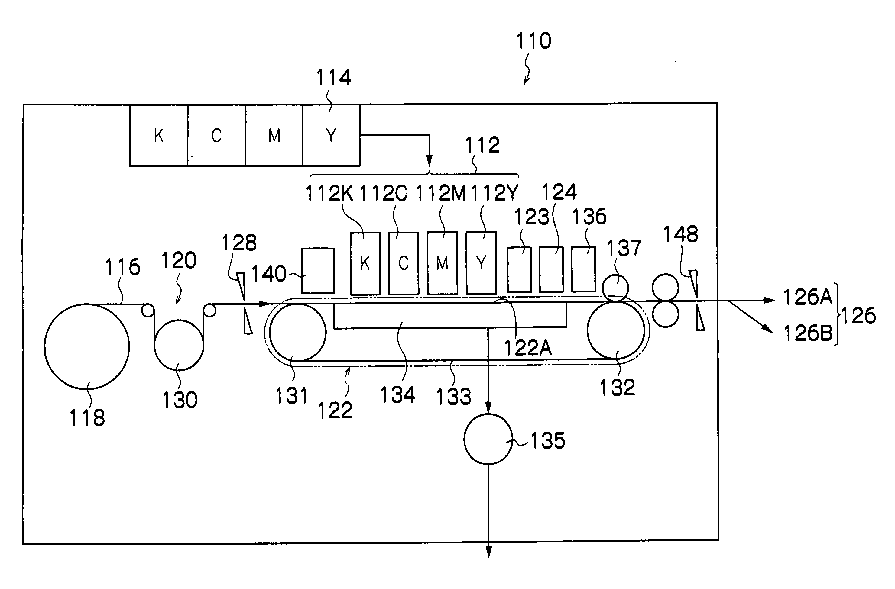
[0181]FIG. 11 is a block diagram showing the composition of an inkjet recording apparatus according to a second embodiment of the present invention. In FIG. 11, elements which are the same as or similar to the composition in FIG. 9 are labeled with the same reference numerals and description thereof is omitted here.

[0182] The inkjet recording apparatus 110′ shown in FIG. 11 is a constitutional example of a mode where the “Calculation method 2” is carried out, which is stated in the description of the “Principles of measurement” given above.

[0183] In other words, the inkjet recording apparatus 110′ shown in FIG. 11 further comprises a high-speed camera 194 as a device which captures an image of the ejection state of each nozzle of the head 150. Furthermore, an image analysis unit 172D is provided in the system controller 172, as a device which analyzes the image signal obtained by the hi...

Example

Modification Embodiment 1

[0195] It is also possible to adopt a mode in which all or a portion of the functions carried out by the droplet ejection error measurement and calculation unit 172A, the density correction coefficient calculation unit 172B, the head adjustment amount calculation unit 172C, the image analysis unit 172D, the density data generation unit 180A, and the correction processing unit 180B shown in FIG. 9 or FIG. 11, are installed in the host computer 186.

[0196] Moreover, the application of the present invention is not limited to a line head type of printer, and embodiments of the present invention can also be applied effectively to a shuttle scanning type of printer.

Example

Modification Embodiment 2

[0197] In the embodiments described above, an error in the relative position between the liquid ejection head and the recording medium is described in terms of an installation error of the head; however, apart from head installation error, the present invention may also be applied with respect to a droplet deposition position error due to the reproducible skewed travel or meandering travel of the medium caused by an installation error in the conveyance unit (for instance, if the belt which conveys the recording medium is installed with an inclination with respect to the head which is installed in a correct installation position), or the like. In this case, a device (mechanism) for adjusting the position of the conveyance device is provided instead of, or in combination with, the head position adjustment mechanism 185.

[0198] It should be understood that there is no intention to limit the invention to the specific forms disclosed, but on the contrary, the in...


PUM


Abstract

The droplet deposition position error measurement method, comprises the steps of: ejecting liquid droplets from a liquid ejection head including a plurality of liquid droplet ejection ports in such a manner that the liquid droplets are deposited on a recording medium; determining an amount of a droplet deposition position error with respect to an ideal droplet deposition position on a recording surface of the recording medium, according to a droplet deposition result obtained from the liquid droplets on the recording medium; separating a first error component caused by an error in a relative position between the liquid ejection head and the recording medium, and a second error component caused by an error in an ejection direction of each of the liquid droplet ejection ports, from the determined amount of the droplet deposition position error; and obtaining error information relating to at least one of the first and second error components.

Description

BACKGROUND OF THE INVENTION [0001] 1. Field of the Invention [0002] The present invention relates to a droplet deposition position error measurement method, a droplet deposition position error adjustment method, a droplet ejection control method and an image forming apparatus, and more particularly, to a droplet deposition position error adjustment method suitable to an inkjet recording apparatus which forms an image by ejecting droplets of ink onto a recording medium from a print head in which a plurality of ink ejection ports (nozzles) are formed, and an adjustment method and a droplet ejection control method for correcting such an error, and an image forming apparatus using this droplet ejection control method. [0003] 2. Description of the Related Art [0004] In an inkjet recording apparatus (an inkjet printer) comprising a print head having a plurality of nozzles, if the print head is installed at angle of inclination with respect to the prescribed installation position (the idea...

Claims


Application Information

Patent Timeline
IPC IPC(8): B41J29/393
CPCB41J29/393B41J2/2135
Inventor YAMANOBE, JUN
Owner FUJIFILM CORP
Why Eureka
Try Eureka