
Decorations with optic fibers

a technology of optic fibers and decorations, applied in the field of illumination optic fibers, can solve the problems of gift not being attractive, and achieve the effects of appealing illumination effect, appealing illumination effect, and enhancing illumination

Inactive Publication Date: 2007-02-01
INNOVATION GLR
View PDF17 Cites 6 Cited by
  • Summary
  • Abstract
  • Description
  • Claims
  • Application Information

AI Technical Summary

Benefits of technology

"The invention is about combining the beautiful illumination properties of optic fibers with the esthetic appearance of decorations like ribbons, bows, and star bows to create an even more beautiful decoration. The decorative item has a base and at least one optic fiber, with the fiber having a base end and a free end. The energy source supplies energy to the light source, and the optic fiber's base end is close to the base of the decorative item. The light source emits light, which enters the optic fiber at the base end and propagates inside it before exiting from the free end to create an illumination effect. The decorative item can also have a decorative body made of ribbon or other material, with the optic fiber embedded in it to create an even more visually appealing effect. The illumination circuitry includes a light source and an energy source, with the optic fibers in contact with the light source at their base end. The optic fibers are distributed through the decorative item to create a small pinpoint of light at the end of each fiber, enhancing the illumination effect. Overall, the invention combines the beauty of optic fibers with the decorative item to create a more visually appealing and special gift or house decor."

Problems solved by technology

The gift does not seem as attractive when the lights are out during, for example, the traditional “blowing out the candles” moment at a birthday celebration or during Christmas Eve when Santa Claus has just dropped the gifts at the foot of the Christmas tree.

Method used


Image

  • Decorations with optic fibers
  • Decorations with optic fibers
  • Decorations with optic fibers

Examples


Embodiment Construction

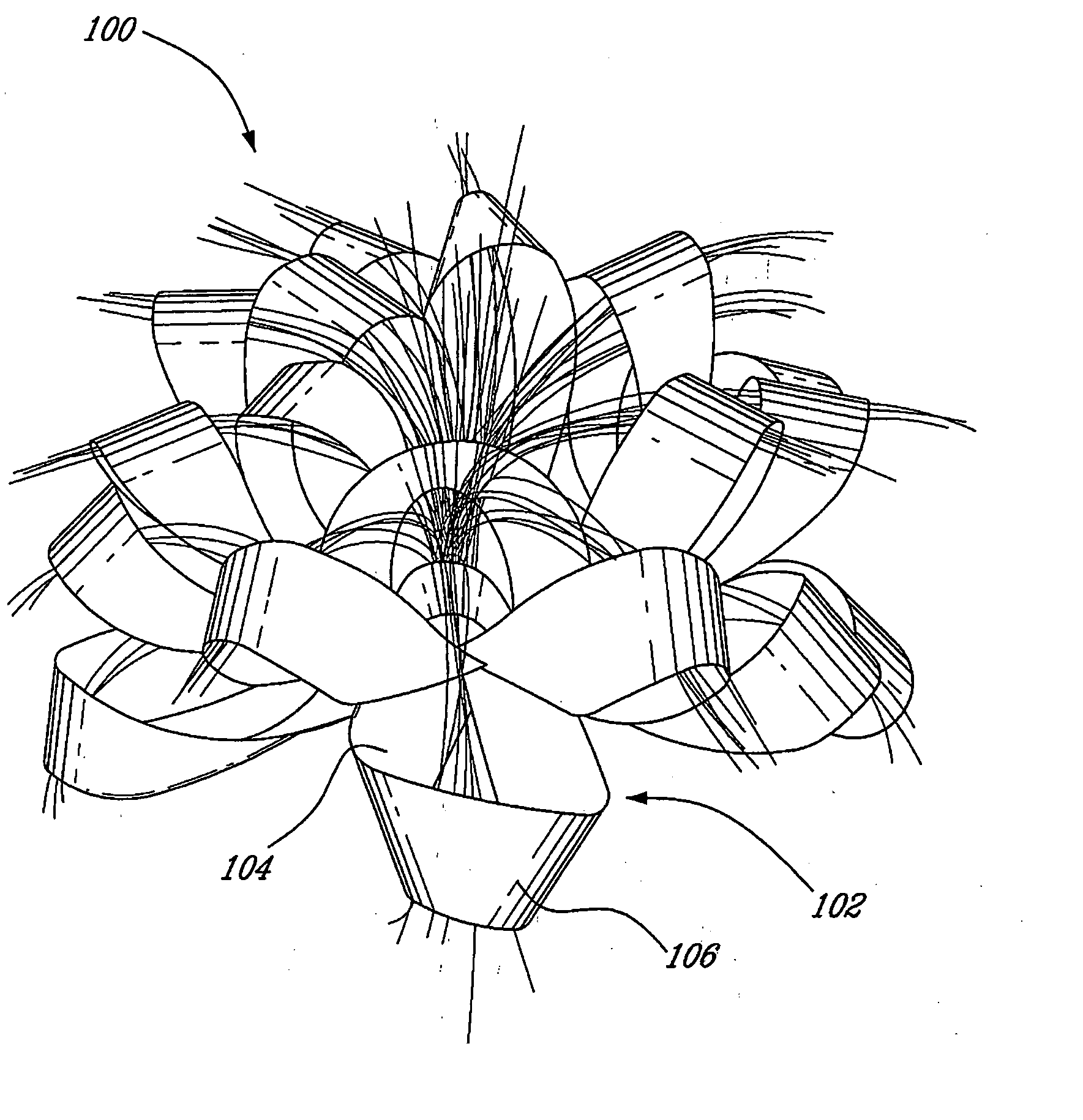
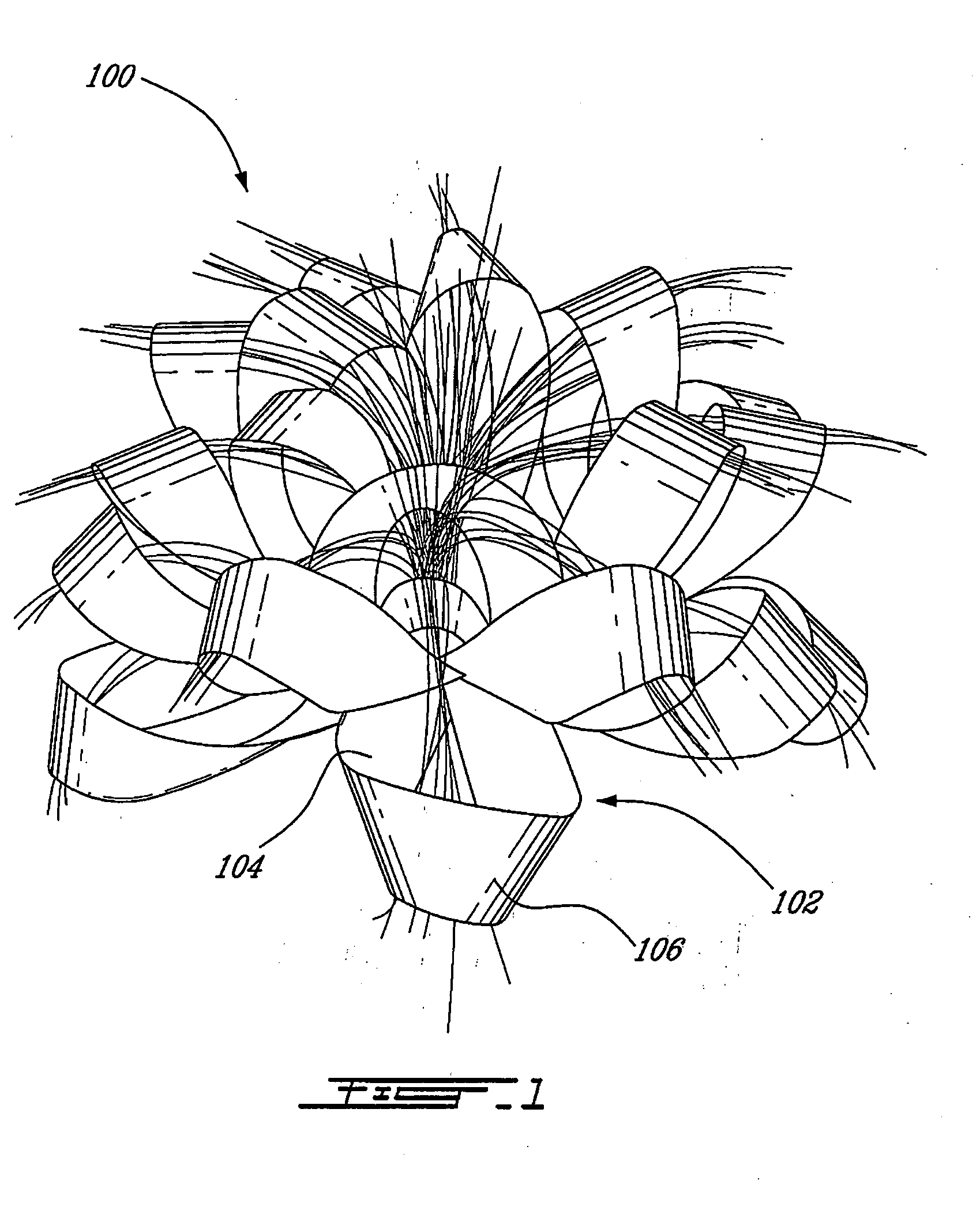
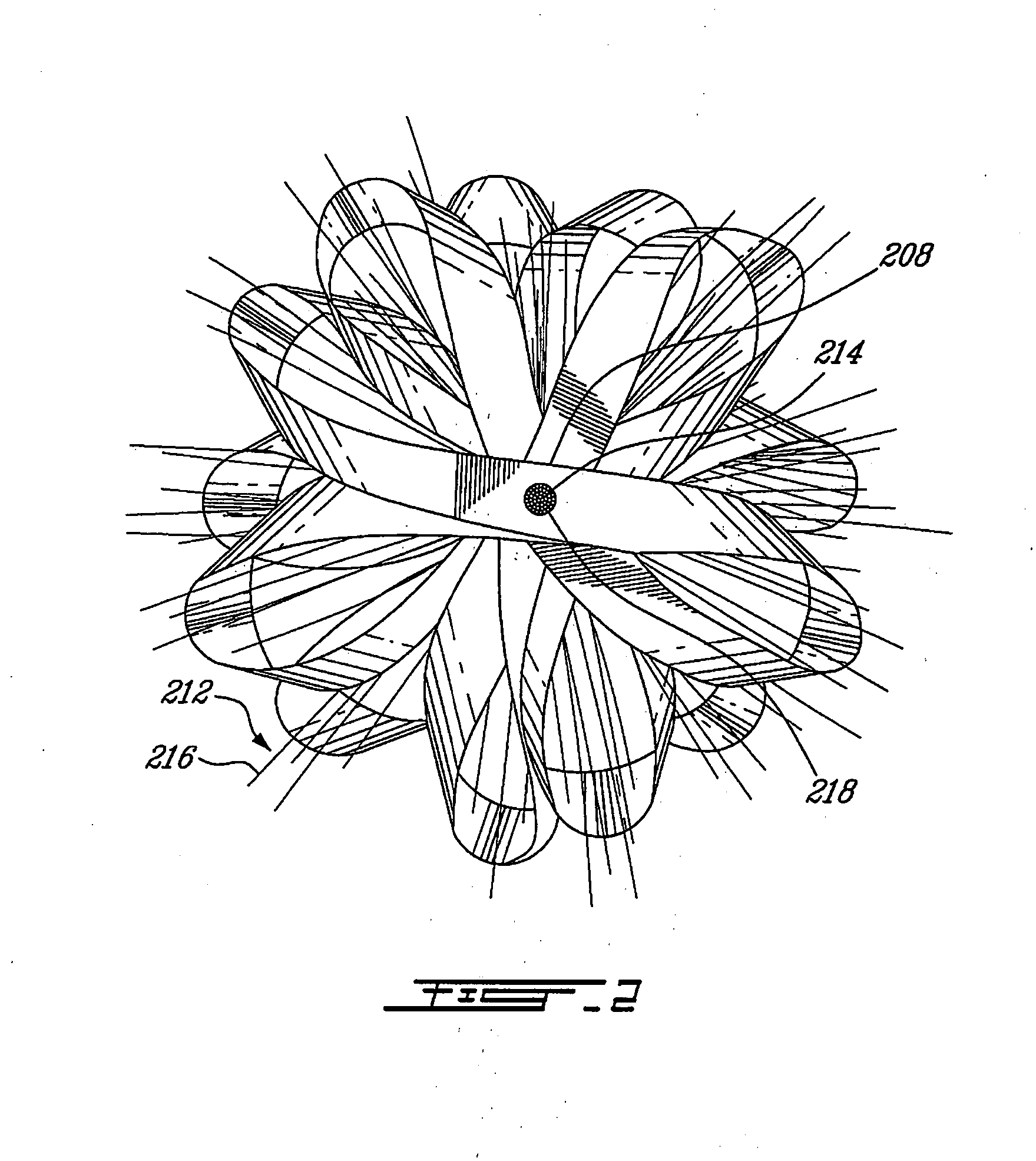
[0030] A preferred embodiment of the optic fiber decorative item is an optic fiber star bow 100, and it is illustrated in FIGS. 1 to 3. The core portion of the optic fiber star bow is a standard star bow 102 consisting of a ribbon 104 which is twisted and turned in a predetermined configuration to create a plurality of loops 106. Each loop 106 is attached to the center of the bow 102 (specifically at its bottom) because the ribbon passes at this point between each loop, thus creating a base 208. The bottom of the bow is generally flat, although some bottom loops may fall below the plane created by the base 208. The loops are generally oriented in an upward fashion, giving the star bow volume, although the external loops are more laterally oriented. The loops are disposed in a generally circular manner around an axis 310 perpendicular to the base so that it creates a flower-head type arrangement.

[0031] The base 208 of the bow is more rigid than the loops due to the ribbon overlappin...


PUM


Abstract

The present invention provides an illuminated decorative item, a decorative item made of ribbon and an illumination circuitry for a decorative item made of ribbon. The illuminated decorative item comprises a decorative body created with at least one elongated strip of material, the body having a base; a light source disposed at the base; an energy source electrically connected to the light source to supply energy to the light source; and at least one optic fiber, each optic fiber comprising an elongated body having a base end and a free end, the base end being close to and oriented towards the light source, the free end being arranged to visually complement the decorative body; wherein the energy source supplies energy to the light source, at least some light emitted by the light source enters the optic fiber at the base end, propagates inside the optic fiber, and exits from the free end thus generating an illumination at the free end and creating a illumination effect for the decorative item.

Description

CROSS-REFERENCE TO RELATED APPLICATIONS [0001] The present application claims priority of U.S. Design application No. 29 / 211,450 filed on Aug. 17, 2004, the specification of which is hereby incorporated by reference.BACKGROUND OF THE INVENTION [0002] 1) Field of the Invention [0003] The present invention relates to the field of illuminated optic fibers used for decoration. [0004] 2) Description of the Prior Art [0005] It is well known in the art that optic fibers are advantageously used in the telecommunications industry to transfer data over long distances. In these applications, photons (making up light) encoded with data are fed into one end of an optic fiber, travel inside the optic fiber and are received at the other end for decoding. One advantage of using fiber optics in telecommunication applications is that optic fibers provide low-loss data transfer, i.e. the signal may travel very long distances with very little attenuation. [0006] An artistic application of optic fiber t...

Claims


Application Information

Patent Timeline
Patent Type & Authority Applications(United States)
IPC IPC(8): F21S4/00
CPCG02B6/0008F21S10/005
Inventor LEMAY, RICHARDGILBERT, LUC
Owner INNOVATION GLR
Learn More