Secondary battery with enhanced connection of protection circuit unit to cap plate

a protection circuit unit and secondary battery technology, applied in the field of secondary batteries, can solve problems such as connection terminal problems, and achieve the effects of preventing connection terminals, enhancing the fixation of lead plates, and improving reliability and mass production quality

Active Publication Date: 2007-02-01
SAMSUNG SDI CO LTD
View PDF6 Cites 26 Cited by
  • Summary
  • Abstract
  • Description
  • Claims
  • Application Information

AI Technical Summary

Benefits of technology

The present invention provides a way for making sure batteries are securely fixed and have good contact between components without exposing them to damage or other issues during manufacturing. This makes it easier to produce reliable products quickly.

Problems solved by technology

This patent describes issues related to connecting components within lithium secondary batteries. Specifically, there are difficulties in securely attaching the lead plate to the cap plate and ensuring proper alignment of the connection terminals. Additionally, current methods result in uneven surfaces and potential leakage points. These technical challenges affect the overall performance and reliability of these batteries.

Method used


Image

  • Secondary battery with enhanced connection of protection circuit unit to cap plate
  • Secondary battery with enhanced connection of protection circuit unit to cap plate
  • Secondary battery with enhanced connection of protection circuit unit to cap plate

Examples


Embodiment Construction

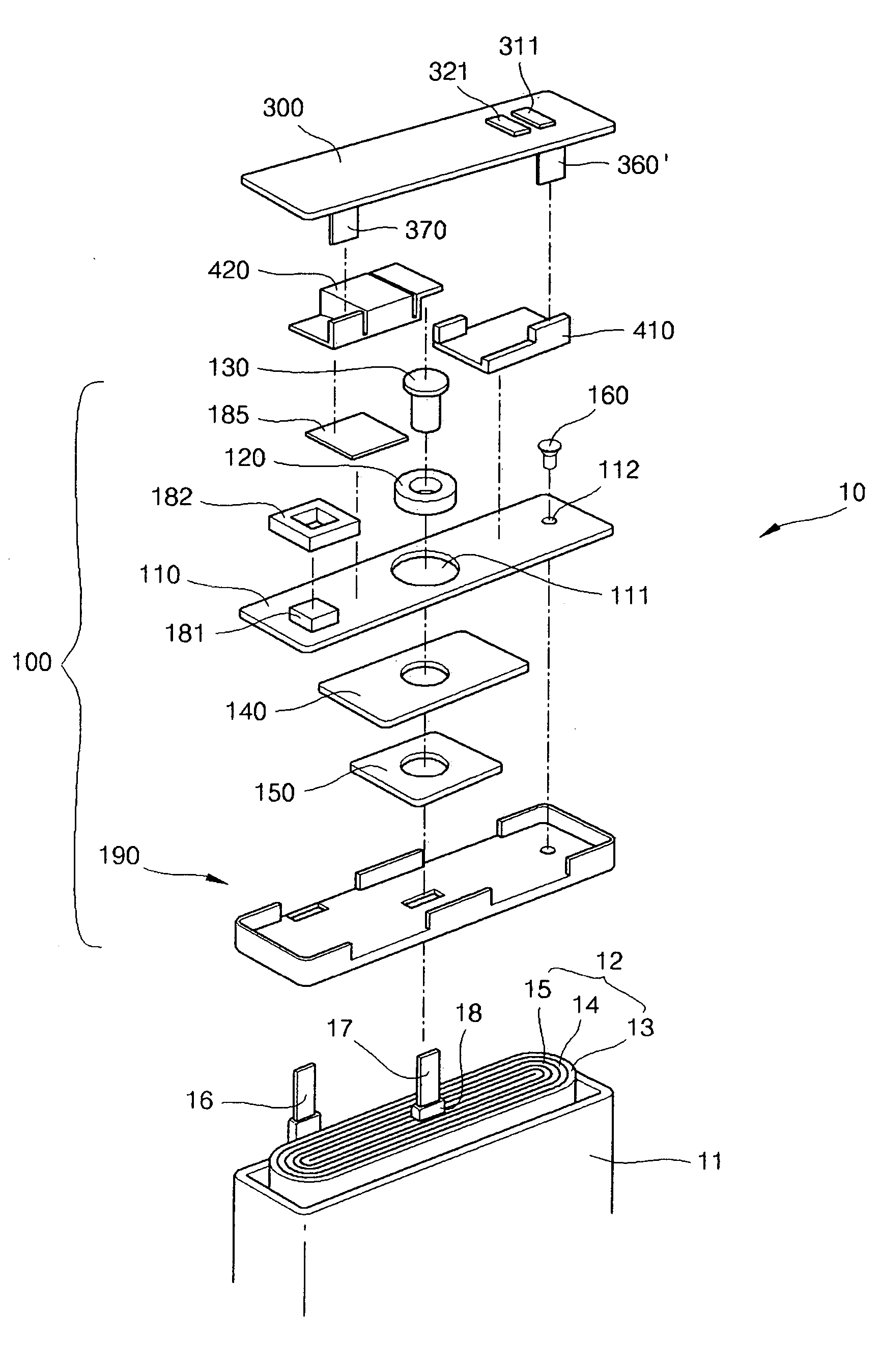
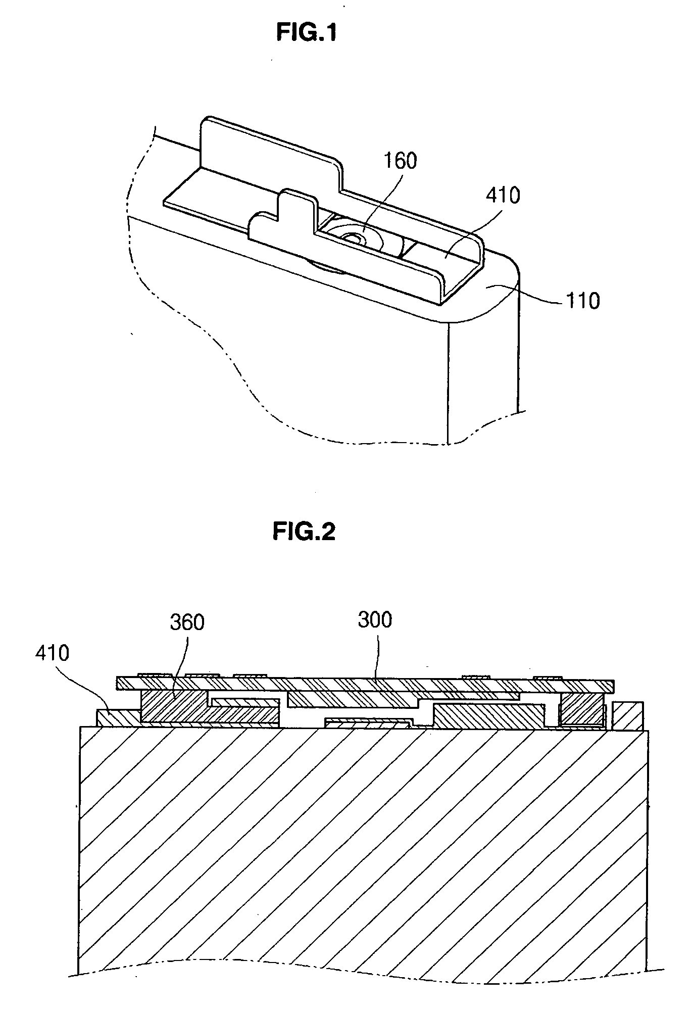
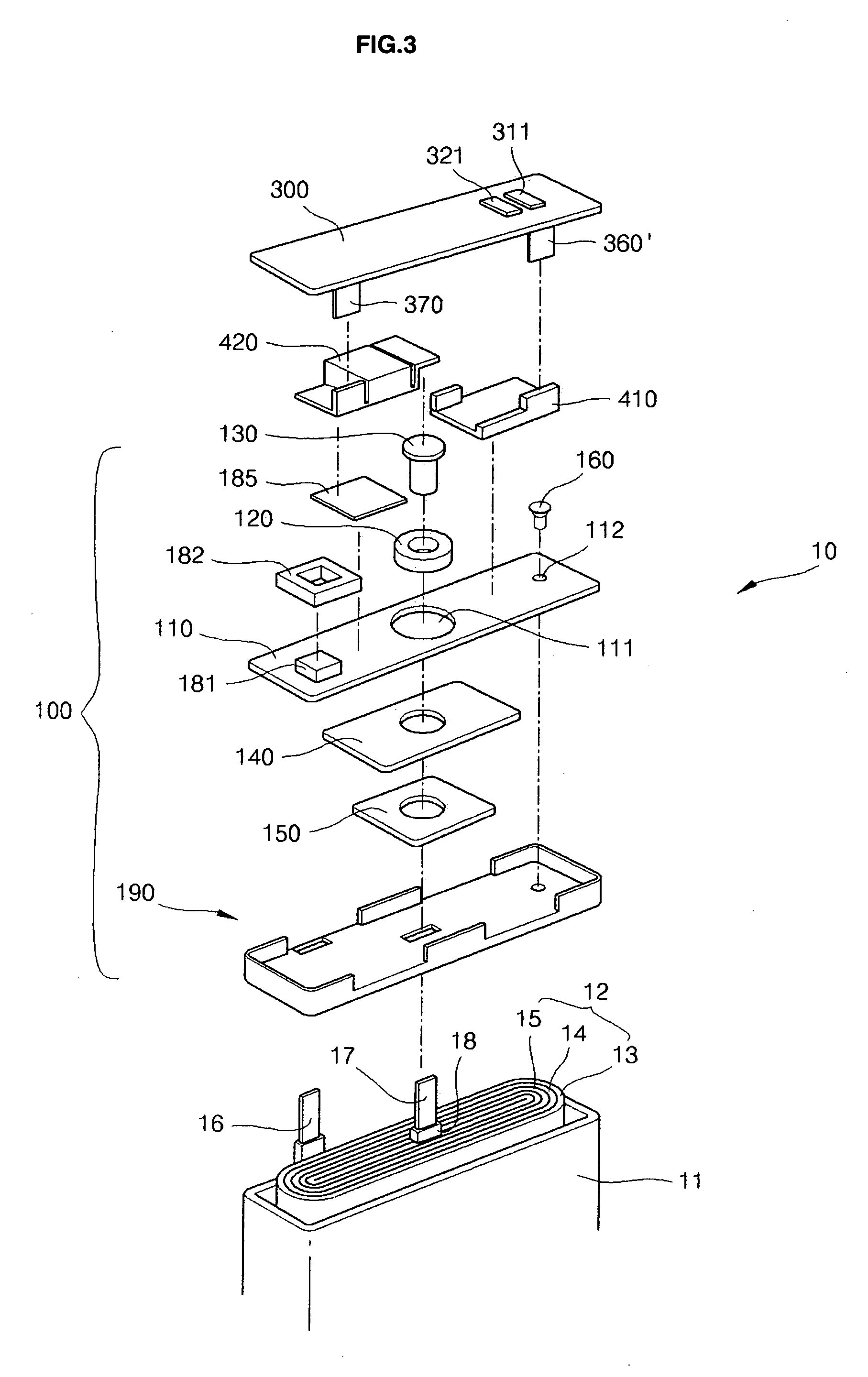
[0024] Referring to FIG. 3, a secondary battery 10 includes an electrode assembly 12 and a can 11 that houses the electrode assembly 12. A cap assembly 100 closes the opening of the can 11 and includes a cap plate 110. A lead plate 410 and breaker 420 are coupled with the upper surface of the cap plate 110. A protective circuit unit 300 is connected to the lead plate 410 and the breaker 420 through connection terminals 360′, 370. A molding resin part (not shown) fills a gap between the cap assembly 110 and the protective circuit unit 300.

[0025] In the electrode assembly 12, after a positive electrode 13 and a negative electrode 15 are formed of wide plates in order to increase electric capacity, a separator 14 for insulating the positive electrode 13 and the negative electrode 15 from each other is interposed between the positive electrode 13 and the negative electrode 15. The positive electrode 13, the separator 14, and the negative electrode 15 are laminated with each other and a...


PUM


Abstract

In the secondary battery, a lead plate is provided so as not to overlap the position of the sealing unit of the electrolyte injection hole to enhance the fixation of the lead plate to the upper surface of the cap plate of a cap assembly. The position of a connection terminal of a protective circuit unit corresponds to the position of the lead plate and together with the connection terminal shape the connection terminal is prevented from being exposed to the outside during hot-melt molding.

Description


Claims


Application Information

Patent Timeline
Owner SAMSUNG SDI CO LTD
Why Eureka
Try Eureka