Ejector-type cycle

a technology of ejector and cycle, applied in the direction of machine operation, transportation and packaging, light and heating apparatus, etc., can solve the problem of inefficiency of conventional techniques, and achieve the effect of improving refrigeration ability

Active Publication Date: 2007-02-08
DENSO CORP
View PDF11 Cites 69 Cited by
  • Summary
  • Abstract
  • Description
  • Claims
  • Application Information

AI Technical Summary

Benefits of technology

[0008] This invention has been developed in view of the situation described above, and the object thereof is to provide an ejector-type cycle in which the refrigerant is branched upstream of the ejector and the refrigeration ability can be improved by utilizing the evaporator efficiently.
[0009] Another object of this invention is to reduce the cost of the ejector-type cycle.
[0011] With this configuration having the dryness degree adjusting mechanism upstream of the ejector, the dryness degree of the refrigerant at the inlet of the first evaporator and the inlet of the ejector nozzle can be adjusted. As a result, the refrigerant at the inlet of the first evaporator can be maintained at a low dryness degree and the first evaporator can be efficiently used for an improved refrigeration ability. Further, in view of the fact that the refrigerant at the inlet of the ejector nozzle can be maintained at a high dryness degree (a large specific volume of the refrigerant can be maintained), the diameter of the ejector nozzle can be increased and the fabrication of the ejector nozzle is facilitated. Thus, the cost of the ejector unit and hence the cost of the ejector-type cycle can be reduced.
[0015] According to this aspect, the refrigerant at the inlet of the first evaporator is held at a low dryness degree and the first evaporator is efficiently utilized to improve the refrigeration ability. Further, by keeping the refrigerant at the inlet of the ejector nozzle at a high dryness degree, the ejector nozzle diameter can be increased to reduce the cost of the ejector unit.

Problems solved by technology

This conventional technique, however, is considered somewhat inefficient in view of the fact that the first evaporator 7 uses the high-temperature, low-pressure refrigerant heated through the second evaporator 8.

Method used


Image

  • Ejector-type cycle
  • Ejector-type cycle
  • Ejector-type cycle

Examples


Embodiment Construction

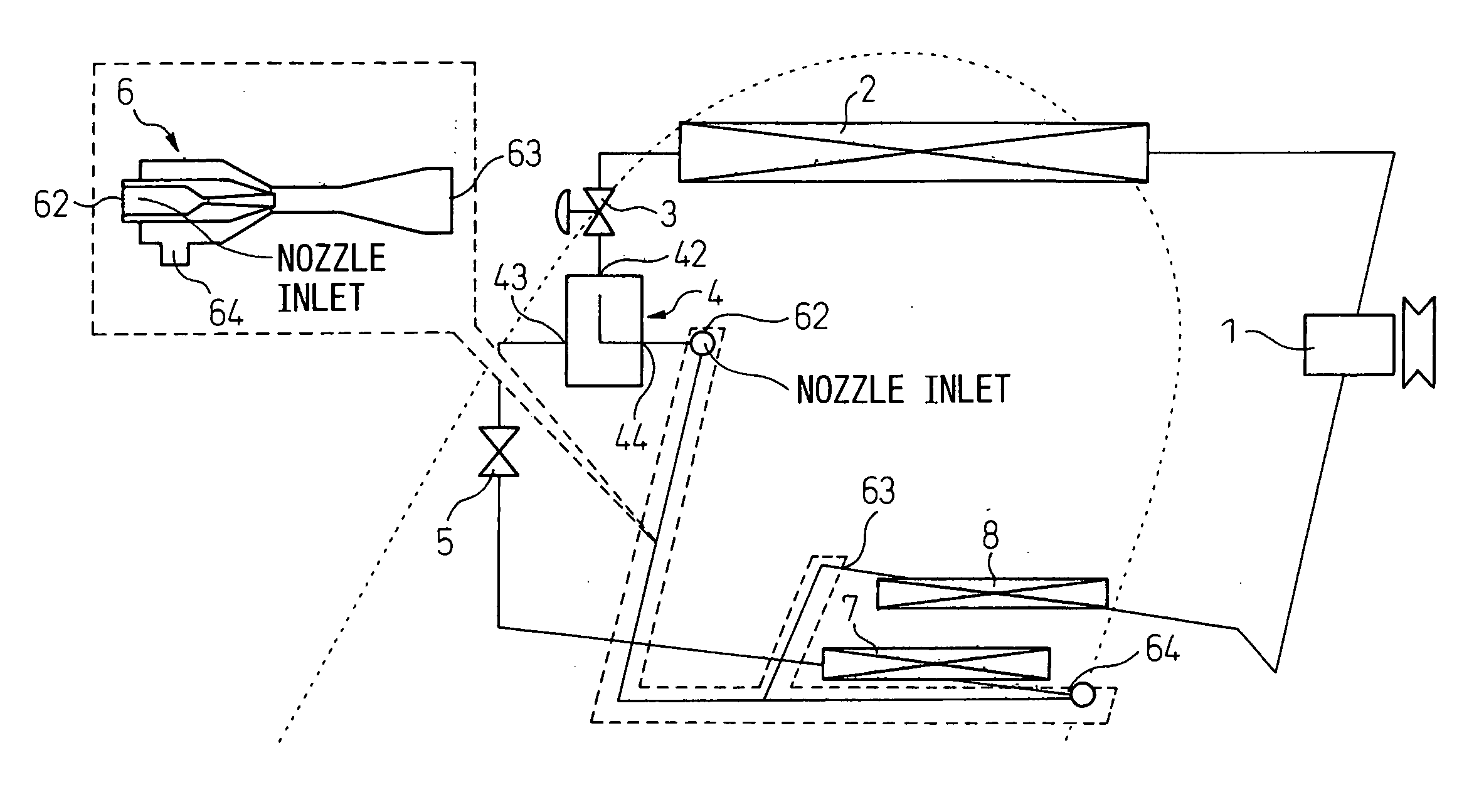
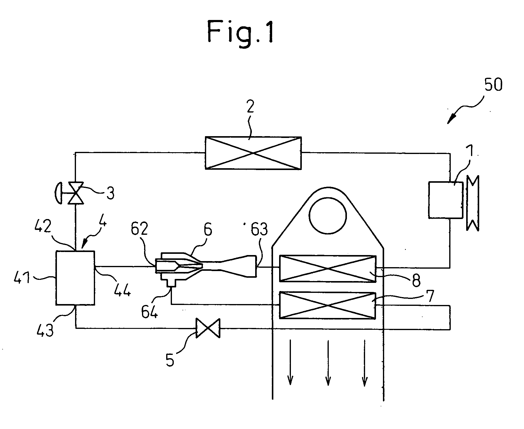
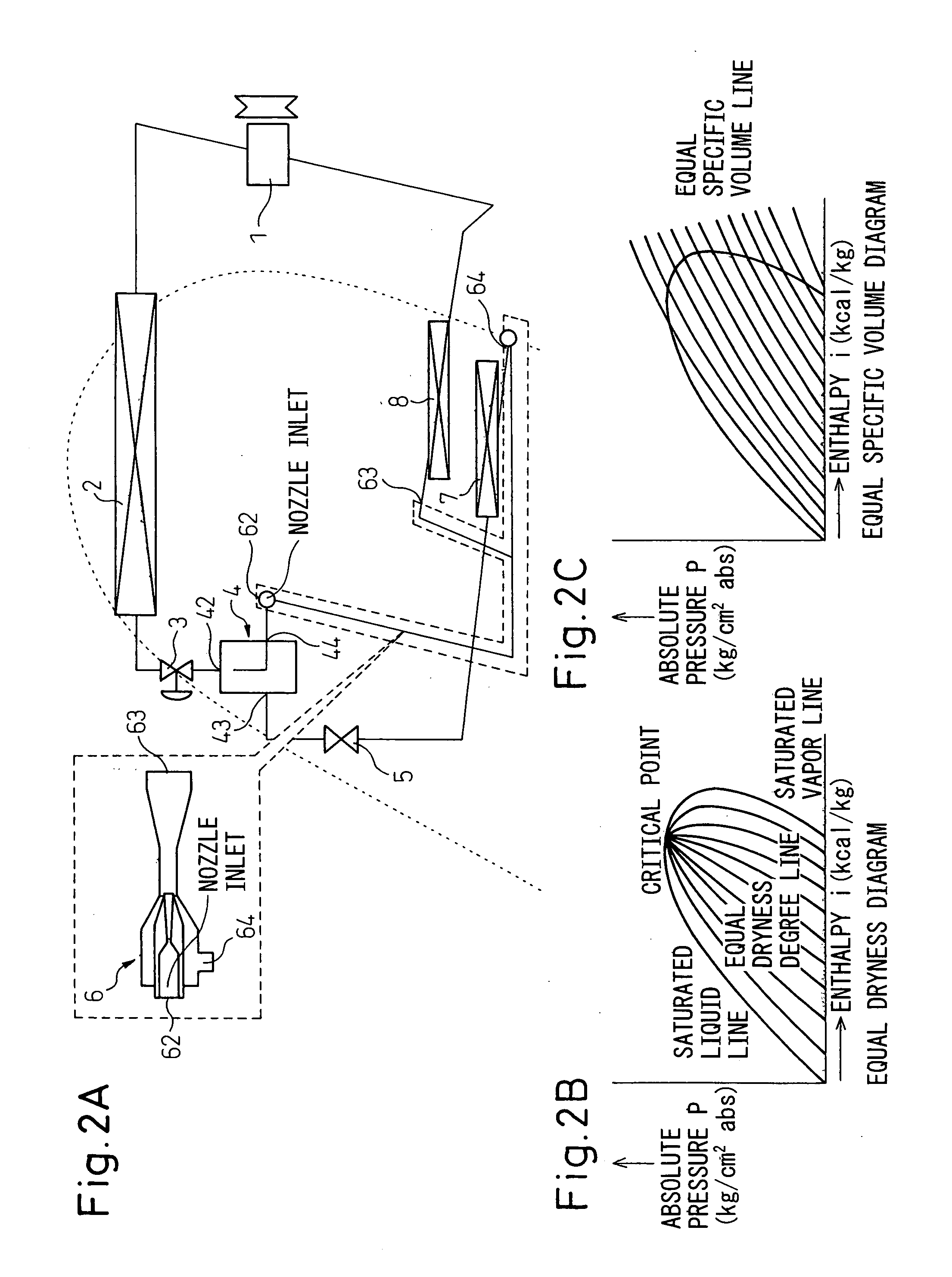
[0029] An embodiment of the ejector-type cycle according to the present invention is explained in detail below with reference to the drawings. FIG. 1 is a diagrammatic view for explaining a first embodiment of the ejector-type cycle according to the invention. In this embodiment of the invention, the ejector-type cycle is used with the climate control system of a vehicle. In FIG. 1, the component elements identical or similar to those of the conventional ejector-type cycle shown in FIG. 6 are designated by the same reference numerals, respectively.

[0030] The ejector-type cycle 50 according to the first embodiment of the invention shown in FIG. 1 comprises a compressor 1 for compressing the refrigerant, a condenser 2 for condensing a high-temperature, high-pressure gas refrigerant, a first orifice mechanism 3 for decompressing the high-temperature, high-pressure refrigerant at the outlet of the condenser 2, a dryness degree adjusting mechanism 4 for separating the refrigerant decomp...


PUM


Abstract

An ejector-type cycle with refrigeration ability improved by utilizing an evaporator efficiently is provided. An ejector-type cycle (50, 60), for exchanging heat using a refrigerant, comprises: a compressor (1) for compressing the refrigerant; a condenser (2) for condensing the compressed refrigerant, a first orifice (3) arranged downstream of the condenser; an ejector (6) arranged downstream of the first orifice and capable of exhibiting a sucking force at the inlet (64) thereof; a first evaporator (7) for exchanging heat with an external fluid by passing the refrigerant and having a refrigerant outlet connected to the inlet (64) of the ejector; a dryness degree adjusting mechanism (4) interposed between the first orifice and the ejector and connected to the ejector and the first evaporator so as to supply the refrigerant thereto, and a second orifice (5) arranged downstream of and connected to the dryness degree adjusting mechanism.

Description

BACKGROUND OF THE INVENTION [0001] 1. Field of the Invention [0002] This invention relates to an ejector-type cycle having an ejector or, in particular, to an ejector-type cycle in which the refrigerant branches at a point upstream of the ejector and which is effectively applicable to the refrigeration cycle of a vehicle climate control system (air conditioner). [0003] 2. Description of the Related Art [0004] The vehicle climate control system (air conditioner) generally uses a refrigeration cycle in which the refrigerant is compressed by a compressor and, after being passed through a condenser, passes through an expansion valve and an evaporator and the air-conditioning air is cooled in the evaporator utilizing the evaporation of the refrigerant. As such a refrigeration cycle, an ejector-type cycle having an ejector arranged before the evaporator is known. The ejector-type cycle is used, for example, in the case where the cooling operation is required to have two temperature bands ...

Claims


Application Information

Patent Timeline
Patent Type & Authority Applications(United States)
IPC IPC(8): F25B19/02F25B1/06
CPCB60H2001/3298F25B5/00F25B2341/0013F25B2341/0011F25B41/00
Inventor YAMADA, ETSUHISATAKEUCHI, HIROTSUGUNISHIJIMA, HARUYUKI
Owner DENSO CORP
Why Eureka
Try Eureka