Sliding screen door

a sliding screen and door technology, applied in the field of sliding screen doors, can solve the problems of abnormal doorframe movement, insufficient suppression of screen expansion due to wind or the like, and achieve the effect of suppressing screen expansion, easy adjustment, and increasing operating for

Inactive Publication Date:
View PDF11 Cites 39 Cited by
  • Summary
  • Abstract
  • Description
  • Claims
  • Application Information

AI Technical Summary

Benefits of technology

[0016] In a sliding screen door having the above-described construction, since a wire adjusting mechanism for adjusting force of repulsion of the aforementioned spring member that occurs when the aforementioned screen is in a stretched condition, by means of adjusting length of the aforementioned wire is installed in the aforementioned vertical frame member, the stretching force of the wire caused when the screen is in the stretched condition can be easily adjusted. Accordingly, the sliding screen door capable of appropriately suppressing expansion of the screen caused by wind or the like can be provided without increasing operating force for an operating doorframe for stretching operation of the screen. In addition, since the aforementioned spring member is brought to a slightly compressed state in the stretched condition of the screen, the wire adjusting mechanism can increase or decrease the force of repulsion of the aforementioned spring member only by means of slightly shortening or lengthening the length of the aforementioned wire. Accordingly, the stretching force of the wire when the screen is in the stretched condition can be easily adjusted.
[0017] Further, in the aforementioned sliding screen door, the aforementioned wire adjusting mechanism is provided with a guide part attached to the vertical frame member and the adjusting member attached to the vertical frame member in a manner so as to be slidable along a longitudinal direction thereof, and so as to be detachable from the vertical frame member at the slid position thereof. Since the length of the wire which is united and fixed to the guide part and the adjusting member is adjusted only by means of sliding the aforementioned adjusting member and by means of adjusting a position where the adjusting member is attached to the vertical frame member, the length of the wire can be easily adjusted. Furthermore, since the length of the aforementioned wire can be adjusted by a moving distance of the adjusting member or by twice as much as the moving distance of the adjusting member, even the moving distance of the adjusting member is short, the stretching force of the aforementioned wire can be fully increased or decreased.
[0018] In addition, since a latching mechanism for automatically latching with a receiving hole formed in the operating doorframe and for locking the operating doorframe at a closing position, when the operating doorframe is moved to the stretch position is installed in the aforementioned vertical frame member, the latching mechanism is automatically latched only by moving the operating doorframe toward the closing position and the operating doorframe can be locked at the closing position. Further, the aforementioned latching mechanism is provided with a position adjusting device for adjusting a lowering position where a latch main body is lowered by its own weight. Therefore, a latching position of the operating doorframe with the latching mechanism can be easily adjusted.
[0019] Furthermore, in the sliding screen door configured to be able to house the screen by means of action force of the aforementioned sinker and the spring member, when the latching of the operating doorframe with the vertical frame member by means of the latching mechanism is carelessly released, there is no guarantee that a dangerous situation does not occur in case the screen is unexpectedly folded. In general, an operation member for releasing the latching is relatively easy to operate when the operation member is configured to be able to release the latching by means of pressing down the same from above. However, in this case, on the contrary, the possibility that the latching is carelessly released is large. However, in the aforementioned latching mechanism, since the latching is configured be released by means of raising the operating member from below at only a certain distance, the latching is not released by relatively careless operation, such as that a hand moved by the side of the operating member touches the same or something taken by hand touches the operating member. In addition, because the latching is released by means of raising the operating member, a hook portion of the latching mechanism can be hooked by force of gravity and there is no need to hook the operating member by a spring or the like, resulting in simplifying the structure.

Problems solved by technology

However, since the stretching force of the wire in the stretched condition of the screen cannot be adjusted, even when the stretching force of the wire in the stretched condition of the screen due to installing of the spring member is excessively strong, although the expansion of the screen due to the wind or the like can further be suppressed, not only large operating force is required to move the operating doorframe toward a stretched position for the operation to stretch the screen, but also the operating doorframe moves at an abnormal speed because strong action force of the spring member is added to the action force of the sinker when a locked state of the operating doorframe is released by a latching mechanism.
Further, when the stretching force of the wire in a case when the screen is in the stretched condition is excessively weak, although the operating force for the operating doorframe for stretching the screen is sufficiently small, there has been a problem that the expansion of the screen due to the wind or the like cannot be sufficiently suppressed.

Method used


Image

  • Sliding screen door
  • Sliding screen door
  • Sliding screen door

Examples


Embodiment Construction

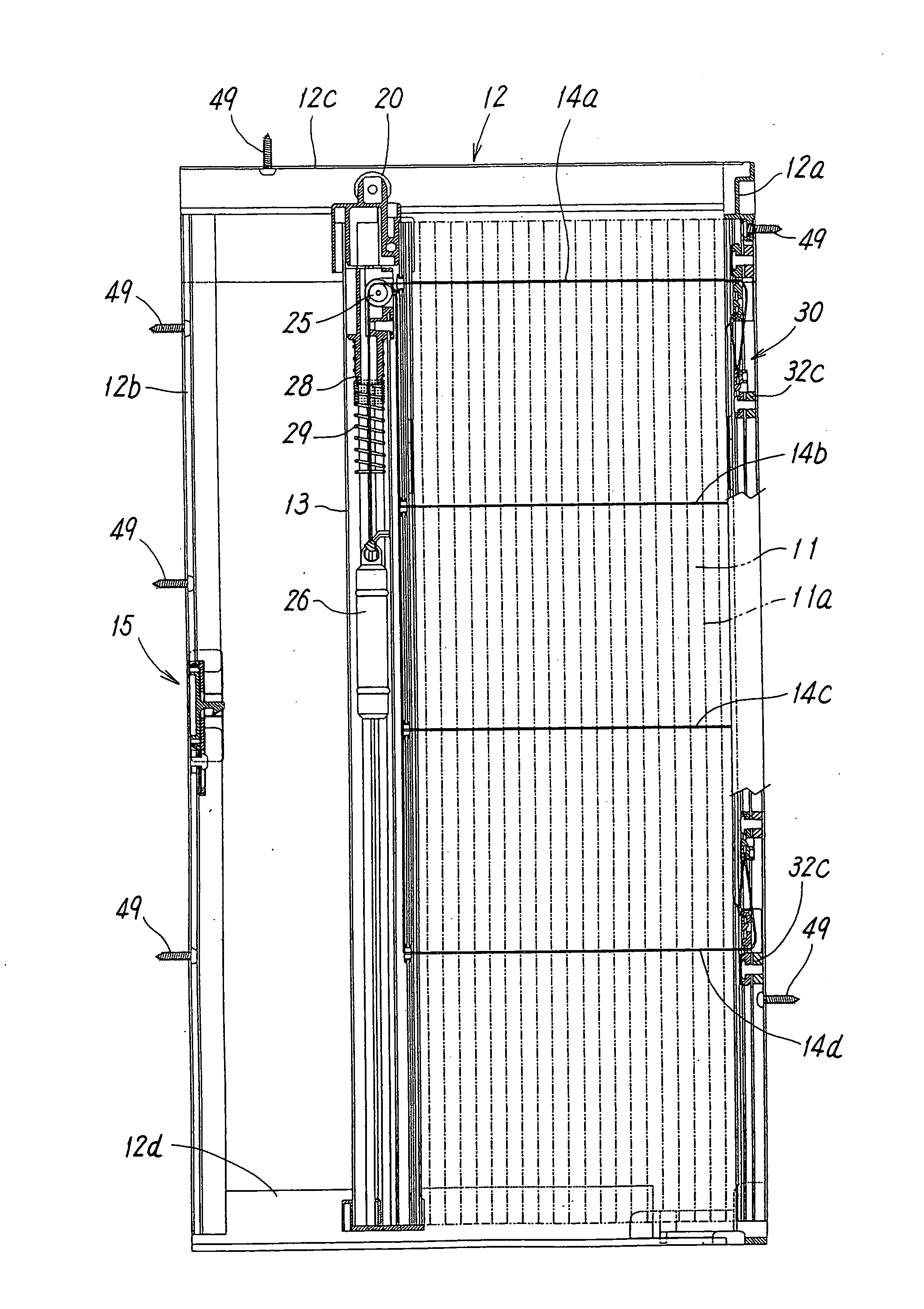
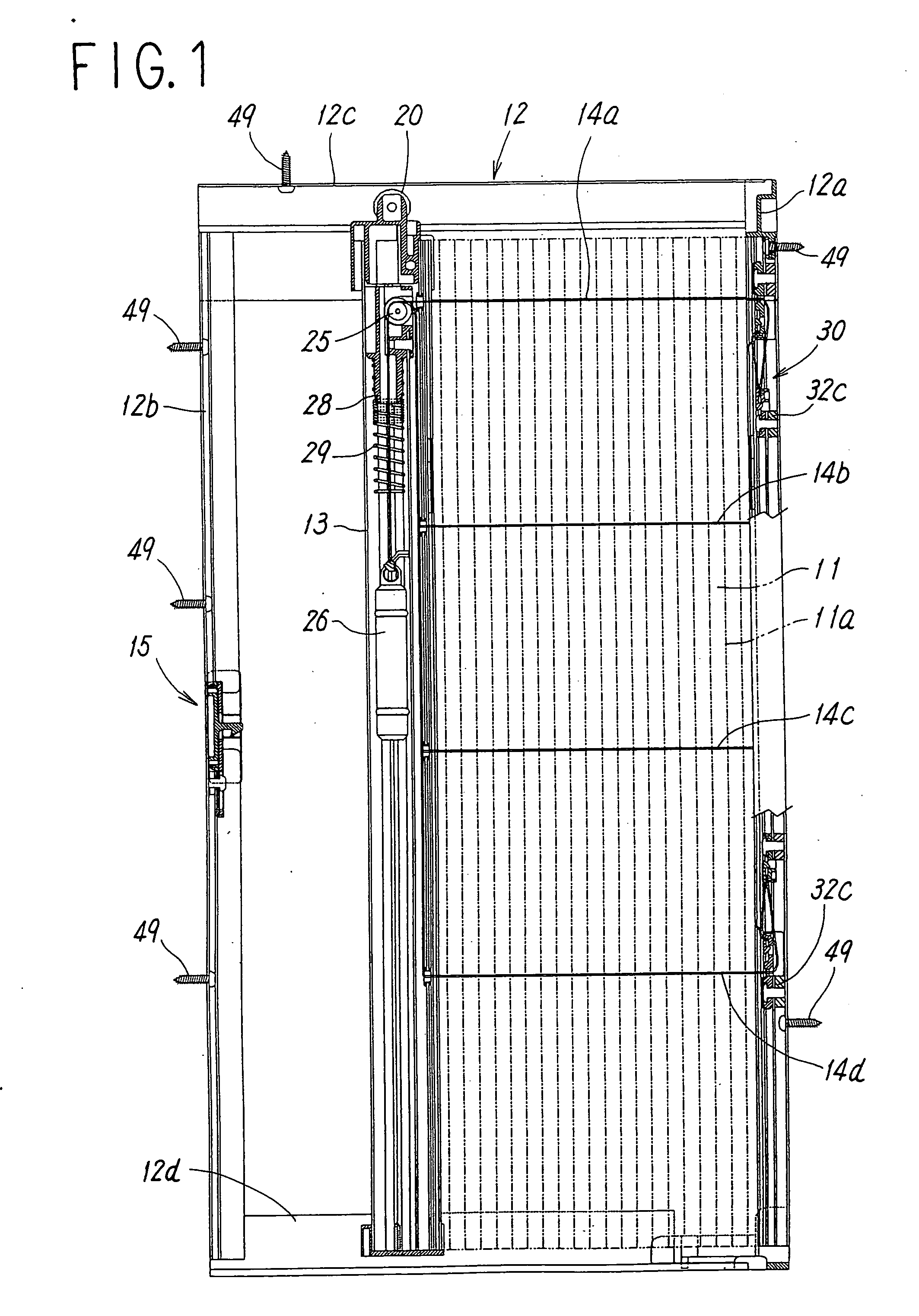
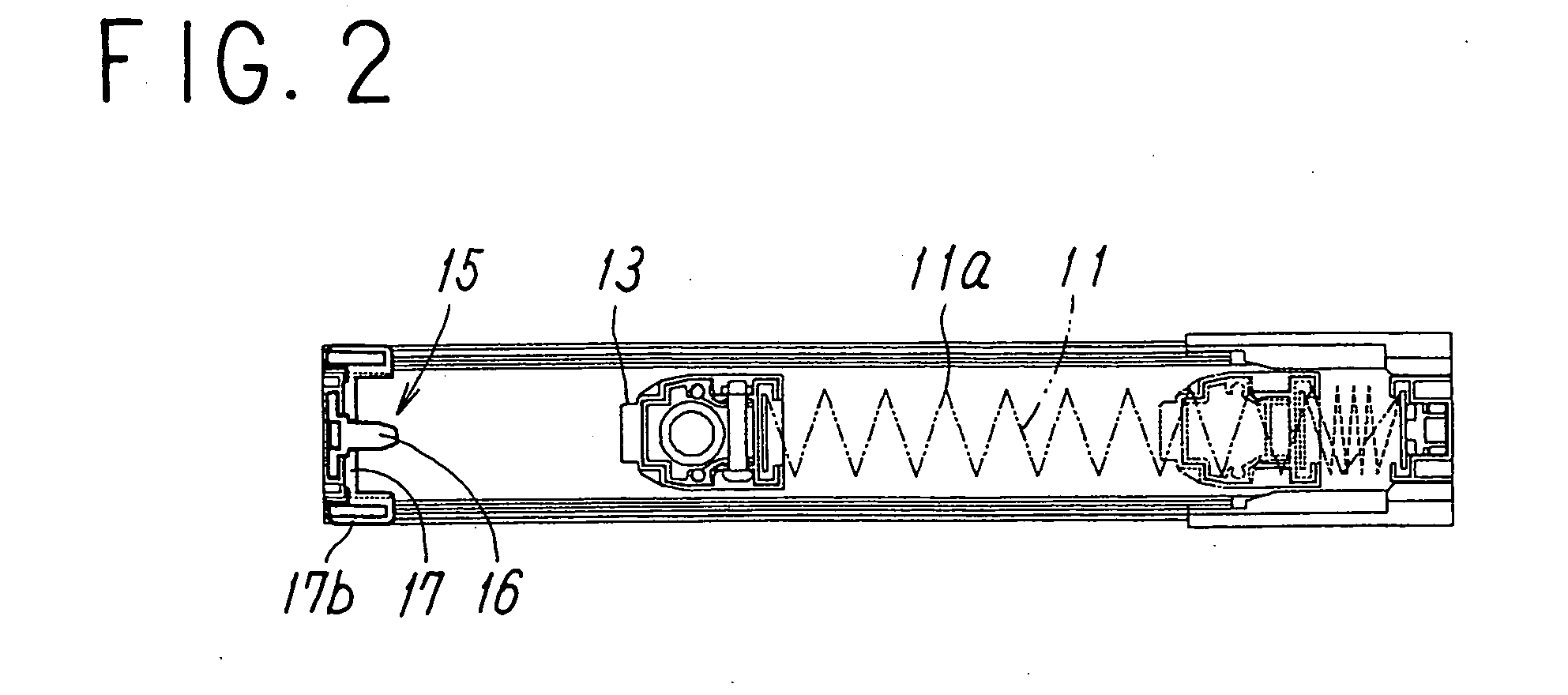
[0037]FIGS. 1 through 17 illustrate the embodiment of a ff with respect to the present invention.

[0038] The sliding screen door is constructed such that a screen 11 for protection from insects is configured to be free for opening and closing in the style of horizontal pulling in a frame member 12 fixed to an opening portion of a building. Further, the screen 11 for protection from the insects is configured to be free for expansion and contraction in the style of an accordion by means of alternately folding in reverse directions at the numbers of folded portions 11a which is in parallel with each other and is spaced at even intervals, as shown in FIGS. 1 and 2. The frame body 12 is constructed by mutually connecting each of a pair of vertical frame members, 12a and 12b made of aluminum or synthetic resin and upper and lower horizontal frame members, 12c and 12d, at four corners.

[0039] One end of the aforementioned screen 11 is fixed to one of the vertical frame members 12a of the a...


PUM


Abstract

A sliding screen door in which stretching force of a wire is easily adjusted when a screen is in a stretched condition, and expansion of the screen caused by wind or the like can be appropriately suppressed without increasing operation force to be applied to an operating doorframe for the operation to stretch the screen. The sliding screen door is constructed such that wires, whose one ends are fixed to a vertical frame member are drooped in the operating doorframe via a guiding member, which is provided in the operating doorframe, after being inserted into the screen, and a sinker is dangled at tip ends of the wires. A spring member is interposed between the sinker and a contacting portion to be a rising uppermost limit of the sinker, and a wire adjusting mechanism for adjusting a length and the stretching force of the wire is installed in the vertical frame member.

Description

TECHNICAL FIELD [0001] The present invention relates to a screen door attached to an opening portion of a building for protection from insects, which is capable of freely opening and closing by horizontally pulling a screen being free for expansion and contraction in a style of an accordion. BACKGROUND ART [0002] A sliding screen door is heretofore known as described in Japanese Unexamined Patent Application Publication No. 2002-371776. In the sliding screen door, a screen configured to be free for expansion and contraction in a style of an accordion by means of alternately folding in a reverse direction at numbers of folded portions being in parallel with each other spaced at even intervals is constructed to be free for opening and closing in a style of horizontal pulling in a frame body. In the sliding screen door, in which one end of the aforementioned screen is fixed to a vertical frame member of the aforementioned frame body and the other end of the screen is attached to an ope...

Claims


Application Information

Patent Timeline
Patent Type & Authority Applications(United States)
IPC IPC(8): E06B9/06E06B9/262E06B9/36E06B9/52
CPCE06B9/262E06B9/36E06B2009/543E06B2009/2625E06B9/52
Inventor MORIYA, HIROFUMIMORIYA, TAKASHI
Why Eureka
Try Eureka