Pressure range delimited valve
- Summary
- Abstract
- Description
- Claims
- Application Information
AI Technical Summary
Benefits of technology
Problems solved by technology
Method used
Image
Examples
Embodiment Construction
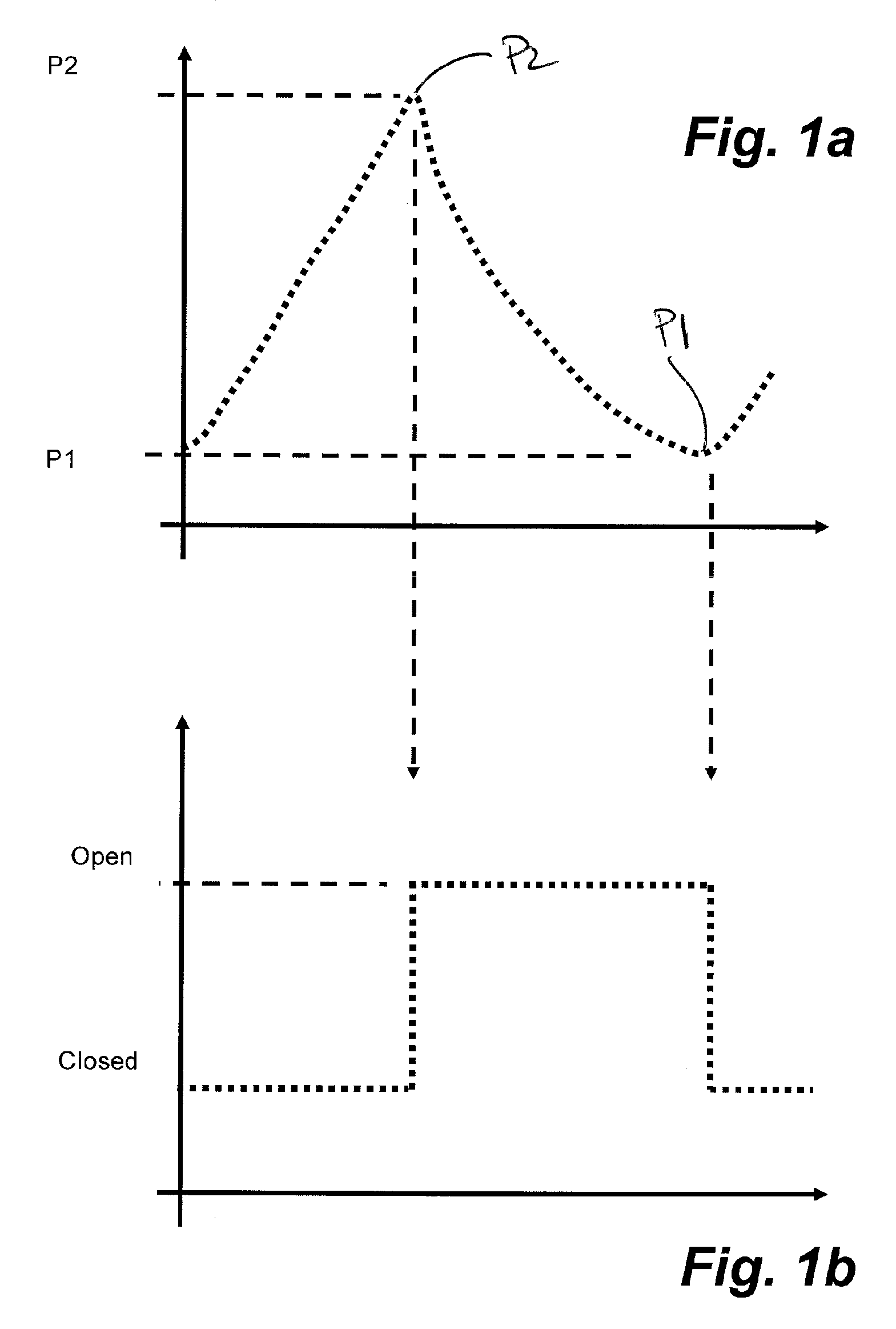
[0027] As shown in FIG. 1a and 1b, the characteristics of a differential pressure valve 10 are illustrated demonstrating the valve being closed at a first pressure P1 and being open at a second pressure P2. The valve is otherwise insensitive to changes in pressure. Intermediate the transition between open and closed positions, the valve is locked in the respective position.
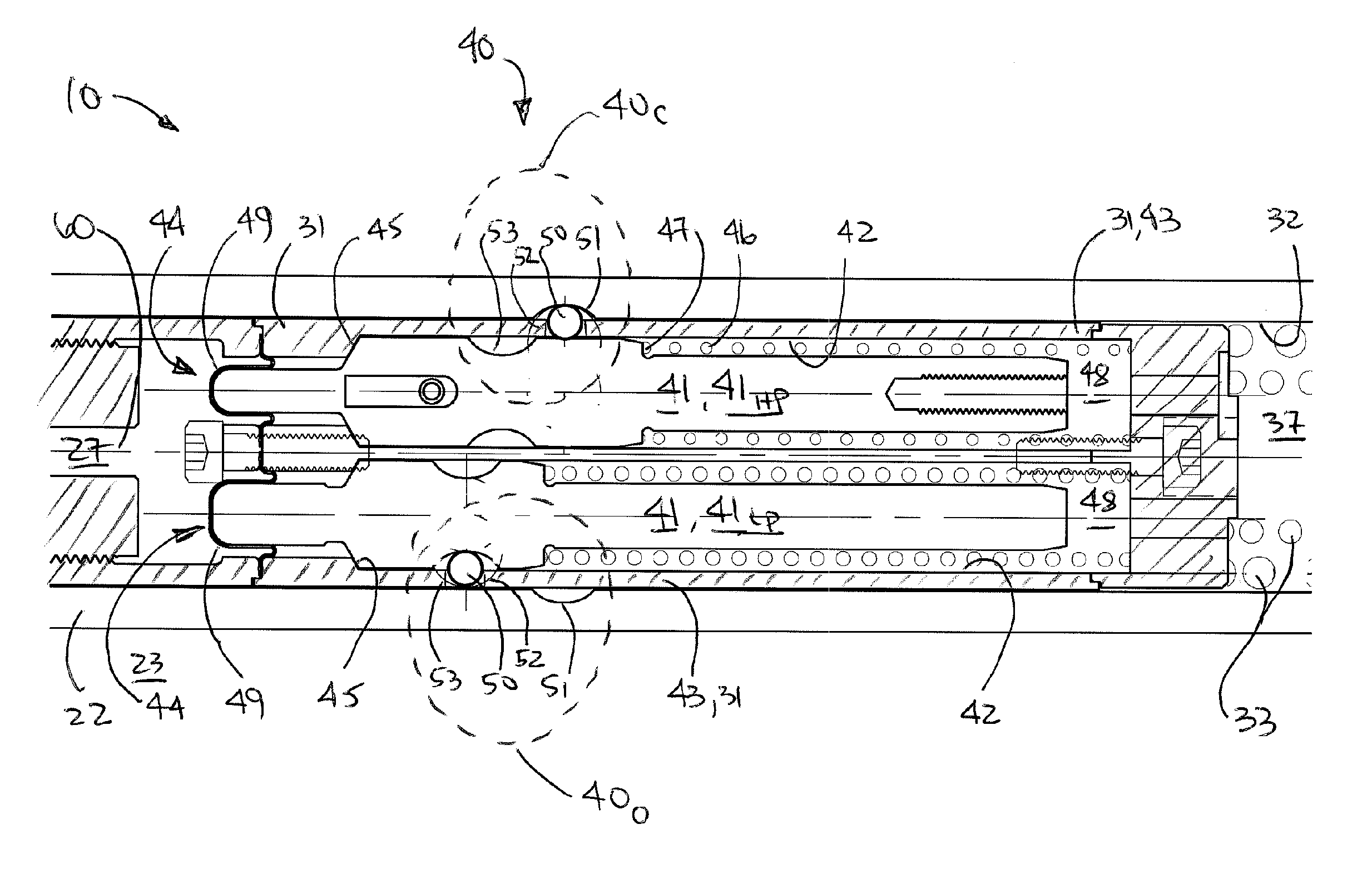
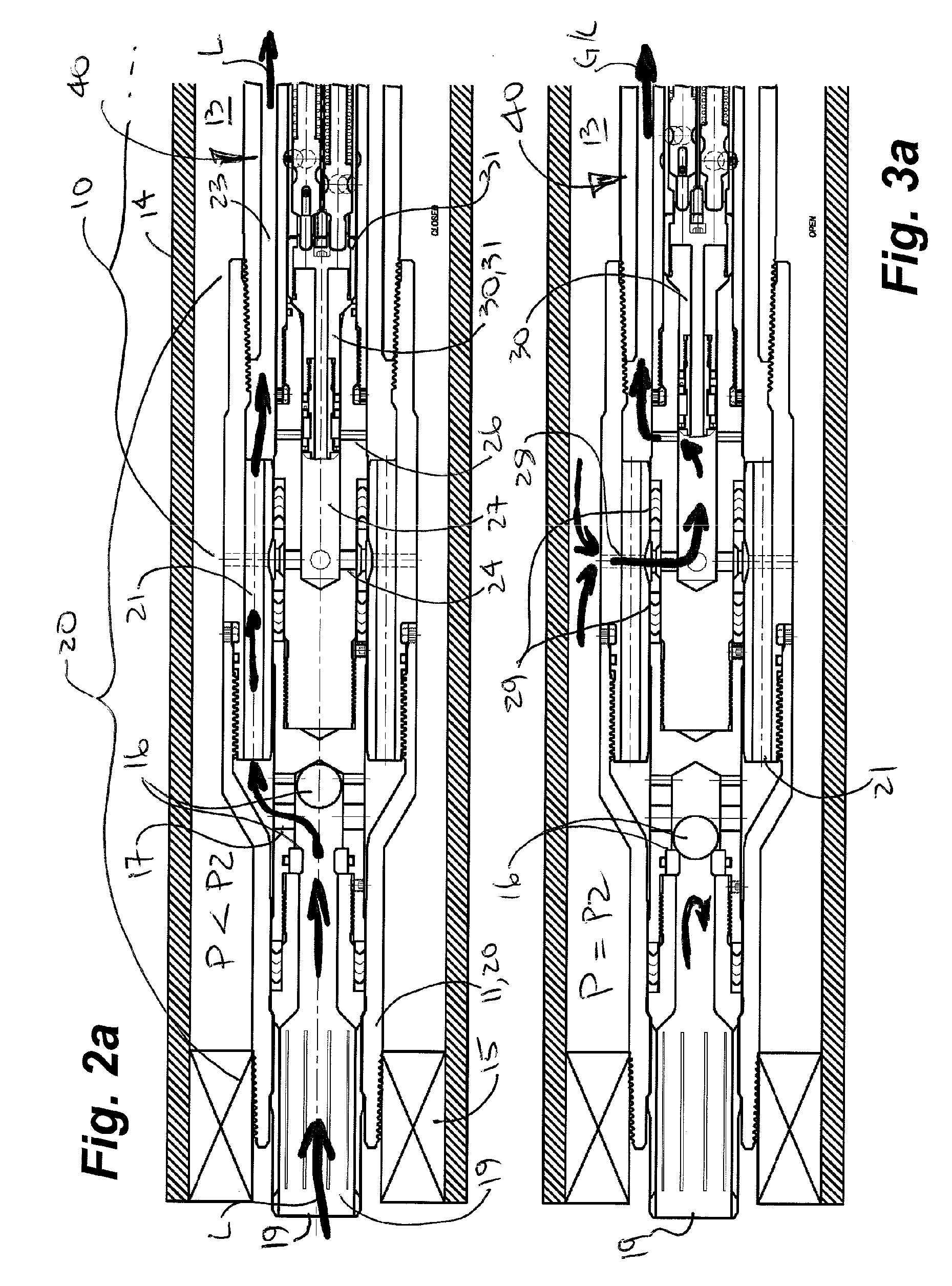
[0028] With reference to FIGS. 2a and 2b, a wellbore implementation is convenient to illustrate the operation of one embodiment of the valve 10 for the control of fluids (L) from a wellbore 9. The valve 10 is illustrated located at a downhole end of a tubing string 11. A wellbore annulus 13 is formed between the tubing string 11 and a casing 14 in the wellbore 9. The tubing string 11 has a bore 12. In this embodiment, a packer 15 seals the wellbore annulus 13 so that wellbore fluid from the wellbore 9 is directed into the tubing string 11 and is isolated from the wellbore annulus 13. In this embodiment, fluid flo...
PUM
 Abstract
Description
Claims
Application Information
 - R&D
- Intellectual Property
- Life Sciences
- Materials
- Tech Scout
- Unparalleled Data Quality
- Higher Quality Content
- 60% Fewer Hallucinations
Browse by: Latest US Patents, China's latest patents, Technical Efficacy Thesaurus, Application Domain, Technology Topic, Popular Technical Reports.
© 2025 PatSnap. All rights reserved.Legal|Privacy policy|Modern Slavery Act Transparency Statement|Sitemap|About US| Contact US: help@patsnap.com


