Thermostatic mixing valve

a technology of mixing valve and thermostatic valve, which is applied in the direction of temperatue control, non-electric variable control, instruments, etc., can solve the problems of uncontrollable piston oscillation and inability to fully terminate the fluid flow from the second fluid inlet into the mixing chamber

Inactive Publication Date: 2007-02-08
GSA IND AUST
View PDF9 Cites 14 Cited by
  • Summary
  • Abstract
  • Description
  • Claims
  • Application Information

AI Technical Summary

Benefits of technology

[0015] A further advantage of the present invention is that in one form entry of the piston into the bore can allow for continued expansion of the thermostatic element, despite the piston being in engagement with the second seat. In the embodiment above in which the annular seal is disposed about the piston, engagement between the piston and the second seat can be maintained despite the thermostatic element continuing to expand and thus continuing to move the piston further into the bore.
[0016] In other forms of the invention, which embody axial engagement, a spring arrangement can be provided, against which the thermostatic element can expand.
[0017] The first fluid seat is preferably formed as a flat face against which an end of the piston engages.
[0018] An adjustment mechanism may be provided to adjust the set temperature of the fluid which passes through the mixed fluid outlet. Preferably, adjustment by the adjustment mechanism results in a change in the proportions of fluid from the respective hot and cold fluid inlets into the mixing chamber so that the set temperature of the fluid flowing through the mixed fluid outlet is adjusted.
[0019] In the preferred forms of the invention, a check valve is mounted adjacent each of the hot and cold fluid inlets to prevent back flow of fluid through the respective inlets.

Problems solved by technology

As discussed above, such a valve has a responsiveness to changes in temperature and / or pressure that can be too great in certain extreme conditions and which can result in the piston oscillating uncontrollably.
While entry of the piston into the bore provides a substantial throttling effect, it does not fully terminate fluid flow from the second fluid inlet into the mixing chamber.

Method used


Image

  • Thermostatic mixing valve
  • Thermostatic mixing valve

Examples


Embodiment Construction

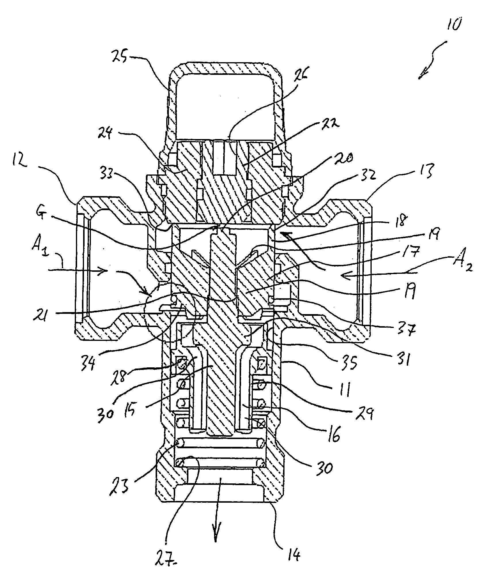
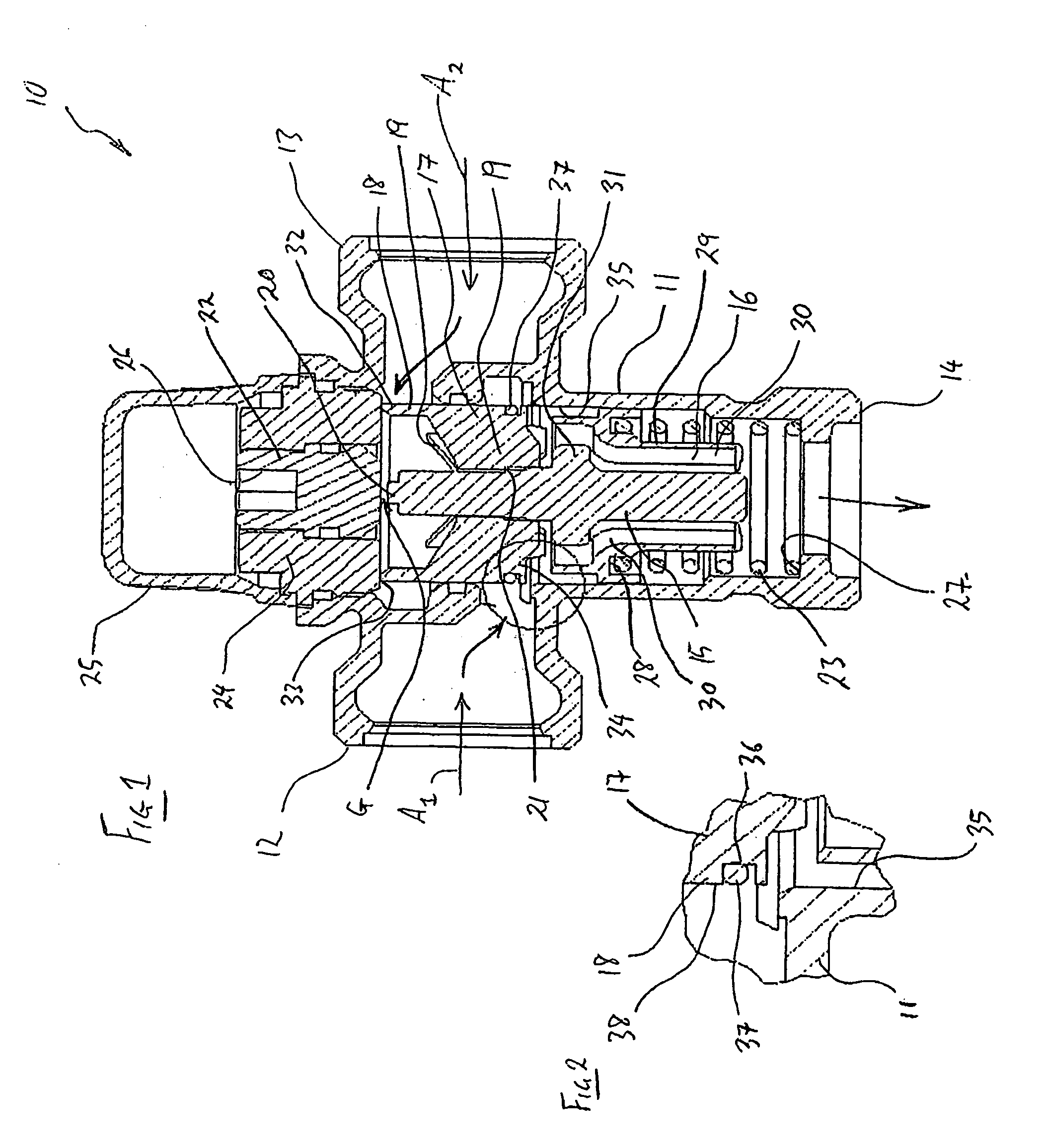
[0023]FIG. 1 illustrates in cross-section, a thermostatic mixing valve 10 in accordance with an embodiment of the invention. The valve 10 includes a valve body 11, a hot fluid inlet 12, a cold fluid inlet 13 and a mixed fluid outlet 14. Each of the inlets 12 and 13 and the outlet 14 are arranged for connection to suitable piping.

[0024] Disposed within the valve body 11 is a thermostatic element 15. The thermostatic element 15 is disposed within a mixing chamber 16 and disposed about an upper end of the element 15 is a regulating piston 17. The piston 17 comprises a cylindrical member 18 and webs 19 which depend from the cylindrical member 18 and which extend to the element 15. In use, fluid can flow into the interior of the cylindrical member 18 for passage through the mixed fluid outlet 14, and the webs 19 provide minimal resistance to that flow. The webs 19 are threadably connected to the element 15 and abut against a step 21 formed on the element 15. In an alternative arrangemen...


PUM


Abstract

A thermostatic mixing valve 10 including a valve body 11 having a first fluid 12 inlet, a second fluid inlet 13 and a mixed fluid outlet 14, a mixing chamber 16 located between the respective fluid inlets 12,13 and the fluid outlet 14. A thermostatic element 15 is located for exposure to mixed fluid and a piston 17 is arranged for movement within the valve body in response to expansion or contraction of the thermostatic element 15. The piston 17 throttles flow of fluid through the first fluid inlet 12 into the mixing chamber 16 by varying its position relative to a first seat 33, and through the second fluid inlet 13 into the mixing chamber 16 by varying its position relative to a second seat formed as a bore 35 into which the piston 17 can progressively enter. Progression of the piston 17 into the bore 35 initially results in a substantial throttling of the flow of fluid from the second fluid inlet 13 into the mixing chamber 16, while further progression results in engagement between the piston 17 and the second seat 35 to terminate the flow of fluid from the second fluid inlet 13 into the mixing chamber 16.

Description

FIELD OF THE INVENTION [0001] The present invention relates to a thermostatic mixing valve. BACKGROUND OF THE INVENTION [0002] Thermostatic mixing valves enable hot and cold fluids, typically water, to be accurately mixed so as to deliver fluid at a desired temperature to the valve outlet. Thermostatic mixing valves typically include separate inlets for ingress of hot and cold water and one outlet for egress of mixed water. [0003] Some thermostatic mixing valves include seats for cooperating with a piston for respectively throttling or isolating the flow of hot and cold fluids through the valve. The need for isolation typically is for safety reasons and it normally is most important to provide for isolation of the hot fluid, so that, for example, a person showering is protected from scalding in the event of the failure of the cold water supply. In such valves, a hard edge of the piston can press firmly against a flat face of the valve body to thereby prevent fluid flow therepast. Th...

Claims


Application Information

Patent Timeline
Patent Type & Authority Applications(United States)
IPC IPC(8): G05D23/13
CPCG05D23/1346G05D23/134
Inventor SCOTT, TONY
Owner GSA IND AUST
Why Eureka
Try Eureka