Safety catheter

Active Publication Date: 2012-07-10
MMI LLC
View PDF55 Cites 11 Cited by
  • Summary
  • Abstract
  • Description
  • Claims
  • Application Information

AI Technical Summary

Benefits of technology

[0004]For the present invention, a safety catheter includes an actuator that interacts with a handle, a shuttle assembly, and a luer assembly. Together, these components cooperate with each other to position a flexible cannula, which is part of the luer assembly, in fluid communication with the vasculature of a patient. In this cooperation, the shuttle assembly interacts with the luer assembly so that a stylet, which is part of the shuttle assembly, stiffens the cannula during its insertion into the vasculature. Once the cannula (i.e. luer assembly) has been properly and effectively established in fluid communication with the vasculature, the stylet (i.e. shuttle assembly) may be safely withdrawn into a chamber that is formed inside the handle. As envisioned for the present invention, however, the actuator controls exactly when this withdrawal of the shuttle assembly and its stylet into the chamber is accomplished.
[0005]In a preferred embodiment of the safety catheter, the actuator is mounted on the handle of the safety catheter, and it is disposed for axial movement thereon between a proximal position and a distal position. Structurally, the actuator includes an annular shaped base member that is positioned on the handle and is centered on the longitudinal axis of the handle. It also has a pair of opposed rails that extend, in parallel, from the base member in a distal direction. Additionally, there is a pair of opposed living hinges on the actuator that are respectively positioned outwardly at a radial distance from the base member. Also, at this same radial distance from the base member, a pair of opposed arcuate bands interconnect the living hinges. Additionally, a dorsal pad is mounted on the base member.
[0006]During an assembly of the safety catheter, a plurality of resilient fingers that extend distally on the handle are engaged with the shuttle assembly. The luer assembly is then positioned to hold the fingers against the shuttle assembly. Specifically, the purpose of this engagement is to stationarily maintain the shuttle assembly in a distal position, relative to the chamber in the handle. Also, with this engagement, the stylet of the shuttle assembly is positioned in the cannula of the luer assembly to stiffen the cannula. Further, the a

Problems solved by technology

Establishing such an access sit

Method used


Image

  • Safety catheter
  • Safety catheter
  • Safety catheter

Examples


Embodiment Construction

[0042]The following description of certain examples should not be used to limit the scope of the present invention. Other features, aspects, and advantages of the versions disclosed herein will become apparent to those skilled in the art from the following description, which is by way of illustration, one of the best modes contemplated for carrying out the invention. As will be realized, the versions described herein are capable of other different and obvious aspects, all without departing from the invention. Accordingly, the drawings and descriptions should be regarded as illustrative in nature and not restrictive.

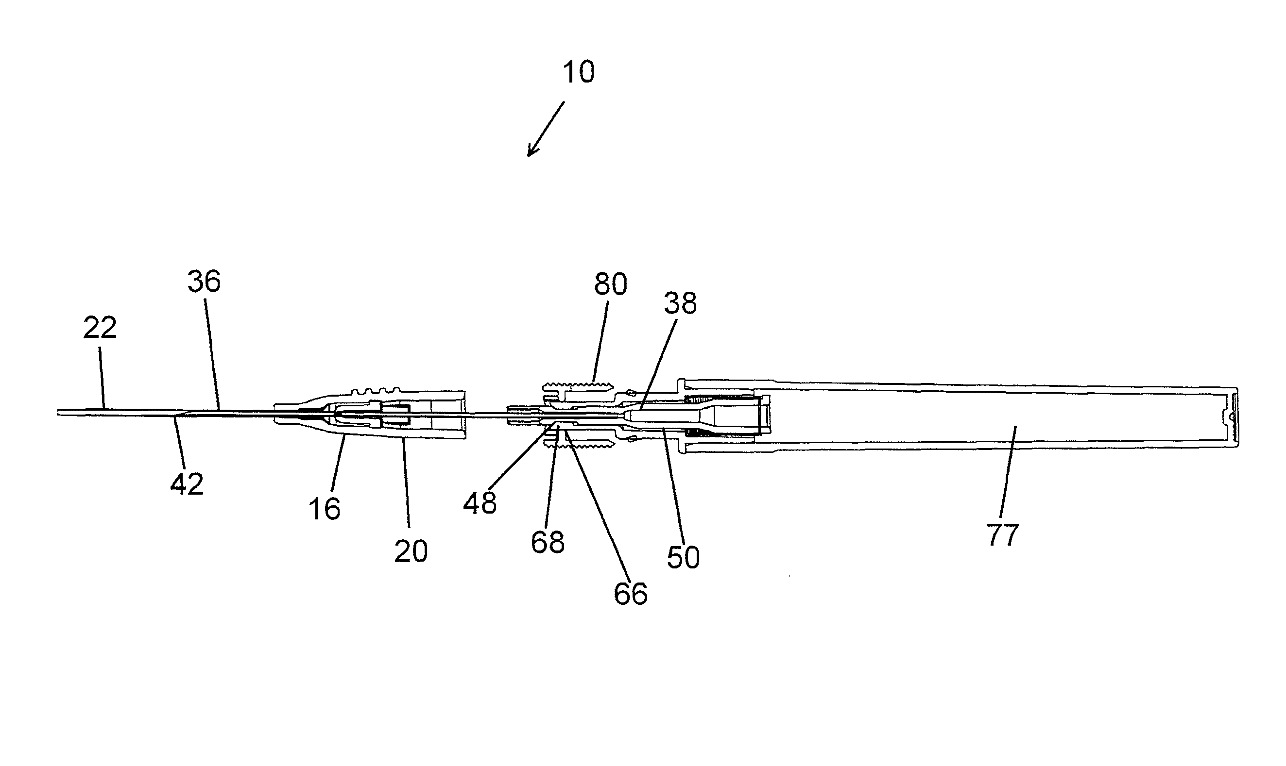
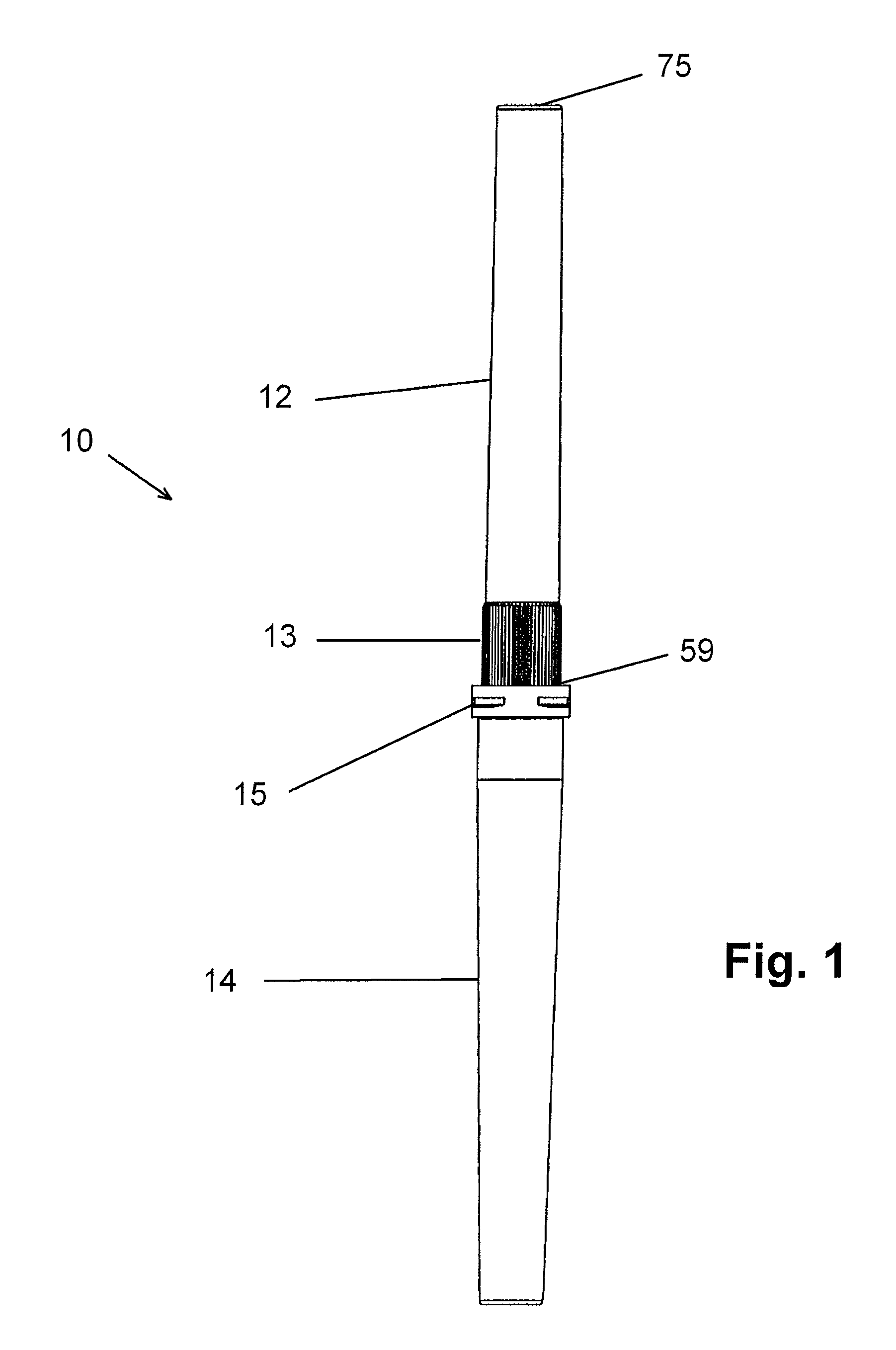
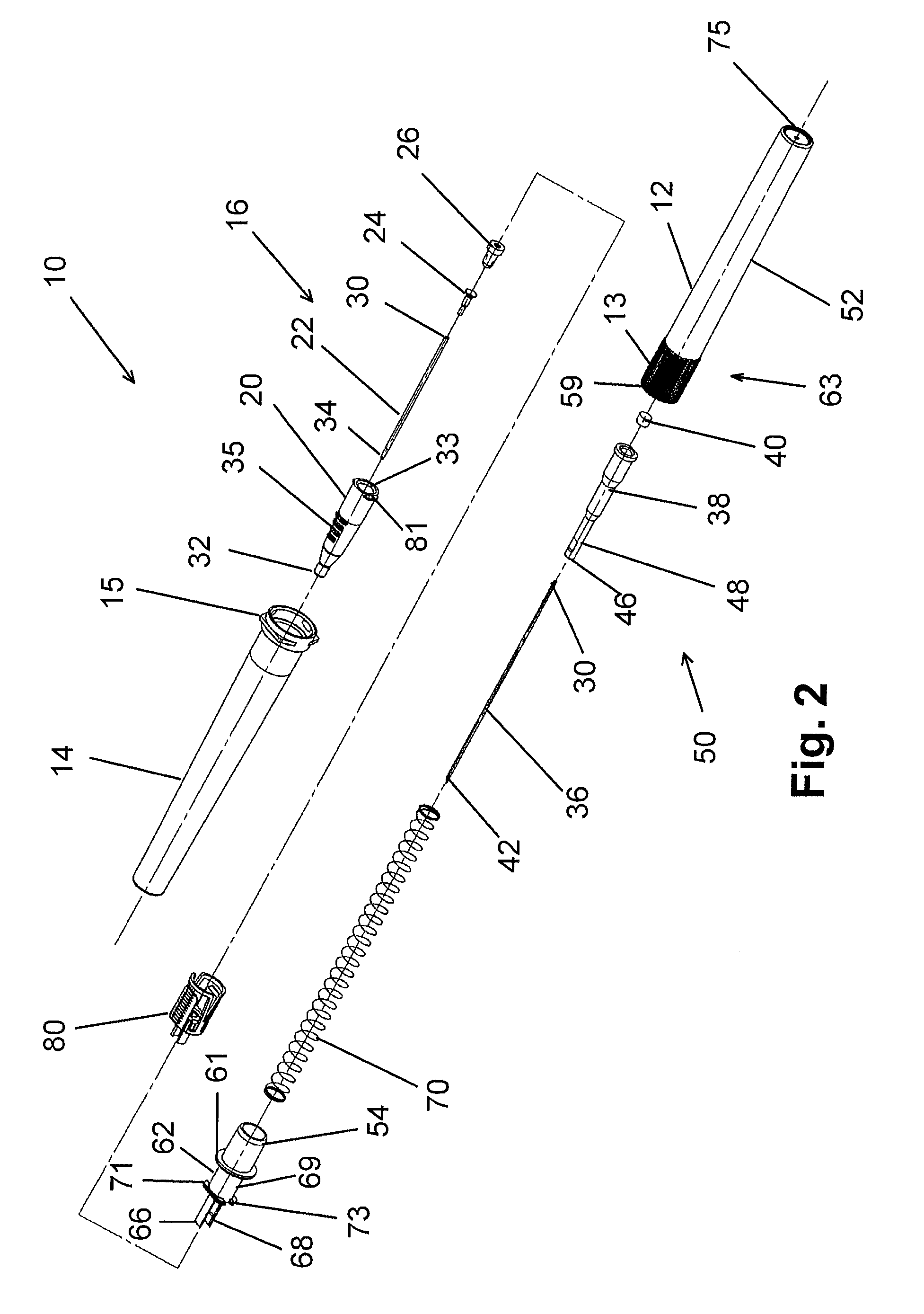
[0043]As shown in the figures, versions illustrated herein may useful as a device for manipulating a stylet and / or any other stiffening or penetration element to position a catheter in fluid communication with the vasculature of a patient, and for subsequently concealing the stylet to prevent inadvertent “sticks” with the stylet. In one version, the retraction of the styl...


PUM

PropertyMeasurementUnit
Distanceaaaaaaaaaa

Abstract

A device and method for positioning a catheter to establish a fluid access site into the vasculature of a patient includes a luer assembly having a cannula or catheter, a shuttle assembly having a stylet for stiffening the catheter, and a holder assembly having an actuator for providing controlled retraction into a handle. The safety catheter comprises a flash window that allows a clinician to view when the vasculature of a patient has been properly accessed and to confirm that the stylet has been fully retracted into a safe position.

Description

PRIORITY[0001]This application is a continuation-in-part of and claims priority to and the benefit of U.S. patent application Ser. No. 12 / 494,108, filed Jun. 29, 2008, entitled Safety Catheter, which is herein incorporated by reference in its entirety.FIELD[0002]Embodiments of the present invention relate, in general, to medical catheters, and, in particular, to devices and methods of use relating to medical catheters having passive safety systems, controlled needle retraction, and visualization windows.BACKGROUND[0003]Fluid access into the vasculature of a patient may be necessary, or desirable, for any of several different reasons. When such access is desirable, a fluid flow path is generally established between an extracorporeal fluid source and the vasculature. Moreover, when an infusion protocol is involved that requires periodic injections, an established fluid access site that can be repetitively used for a sequence of different injections may be required. Establishing such a...

Claims


Application Information

Patent Timeline
IPC IPC(8): A61M5/178
CPCA61M5/158A61M25/0043A61M25/0009A61M25/0631A61M2005/1588A61M2005/1587Y10T29/49826Y10T29/49863A61M5/3257A61M25/0693
Inventor MILLERD, DONASBAGHI, HOOMAN
Owner MMI LLC
Why Eureka
Try Eureka