Cleaner head

a cleaner head and cleaning head technology, applied in the field of cleaner heads, can solve the problems of debris trapped between the bristles, dust particles or other relatively small items of debris to be dislodged from the tufts of bristles, and debris such as fibers and hairs to be dislodged, so as to facilitate the use of the cleaner head and maximize the likelihood of the bristles

Inactive Publication Date: 2012-06-14
DYSON TECH LTD
View PDF0 Cites 13 Cited by
  • Summary
  • Abstract
  • Description
  • Claims
  • Application Information

AI Technical Summary

Benefits of technology

[0021]Each body is preferably inclined relative to the plane of the opening so that, with rotation of the agitator, the bristles protrude through the opening towards the front of the opening. This can facilitate the use of the cleaner head for the removal of individual hairs or a clump of hairs from a surface, as a user instinctively locates the cleaner head immediately behind the hairs to be removed and moves the cleaner head over the hairs so that at least the front portion of the cleaner head passes over the hairs. Locating the area of the surface which is swept by the bristles beneath and towards the front of the opening can maximize the likelihood that the bristles will come into contact with the hairs during the rotation of the agitators.
[0022]As an alternative to locating the bristles or other surface engaging members on a flexible body, the bristles may be located on a substantially rigid body which is moveable relative to the drive shaft of the agitator upon engagement between the tip of the bristle and the surface to be cleaned. For example, the body may be connected to the drive shaft by a flexible coupling or a universal joint which allows the body to move relative to the drive shaft upon engagement between the tip of the bristle and the surface to be cleaned. The flexible coupling may allow the body to move along the rotational axis of the drive shaft upon engagement between the tip of the bristle and the surface to be cleaned, or it may allow the body to pivot relative to the drive shaft upon engagement between the tip of the bristle and the surface to be cleaned.

Problems solved by technology

As the bristles are swept between the fibers, the force applied to the bristles by the carpet causes the bristles to splay, resulting in some debris becoming lodged between the bristles.
As the bristles are rotated away from the fibers, the motion of the bristles as they return to their normal configuration tends to cause dust particles or other relatively small items of debris to be dislodged from the tufts of bristles.
However, debris such as fibers and hairs can remain trapped between the bristles.
While reducing the risk of the brush bar stalling during the cleaning of deeply piled carpets, the provision of soft bristles and / or a low number of bristles tufts can impair the cleaning performance of the cleaner head when used on short piled carpets.

Method used


Image

  • Cleaner head
  • Cleaner head
  • Cleaner head

Examples


Embodiment Construction

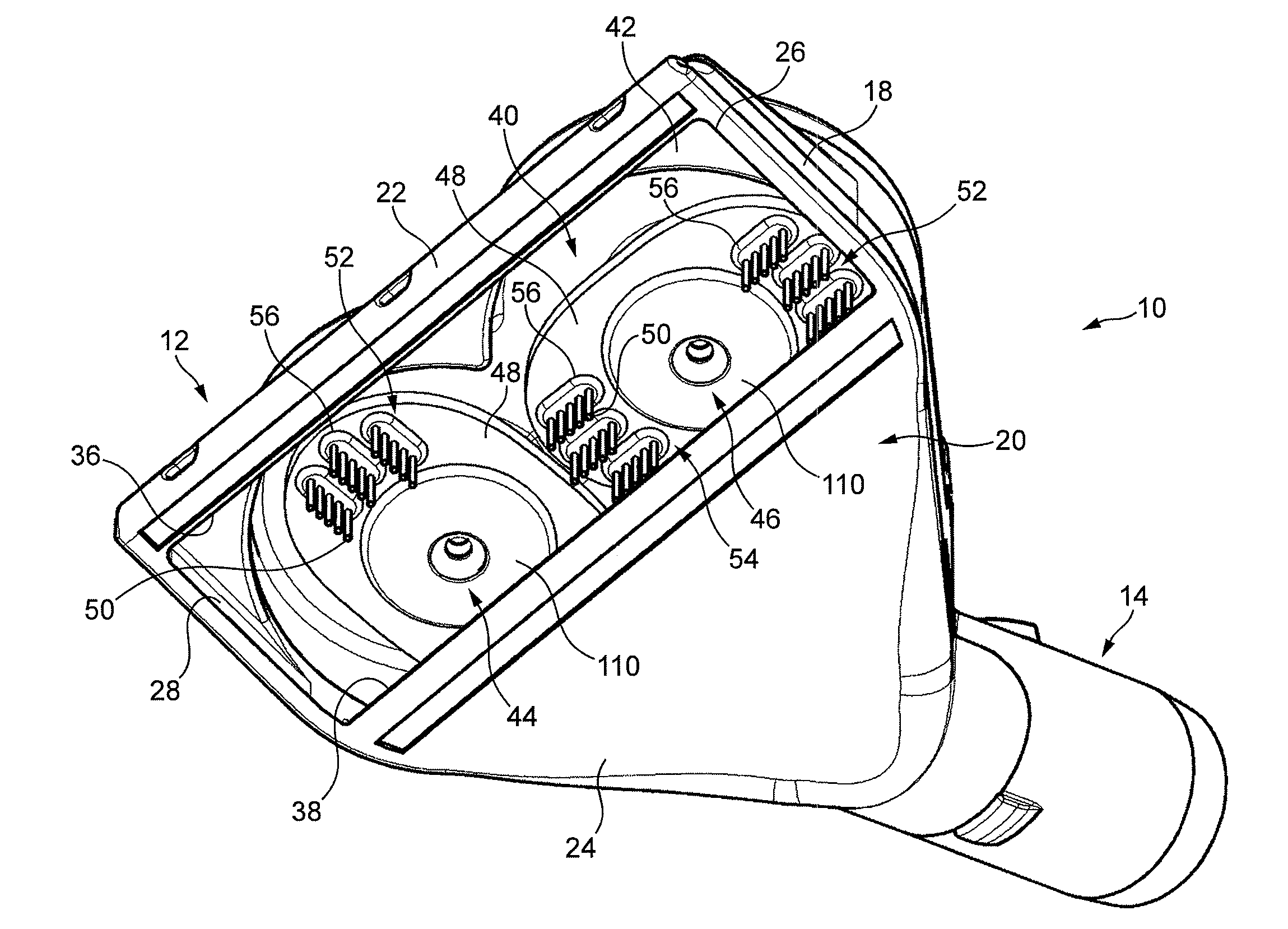
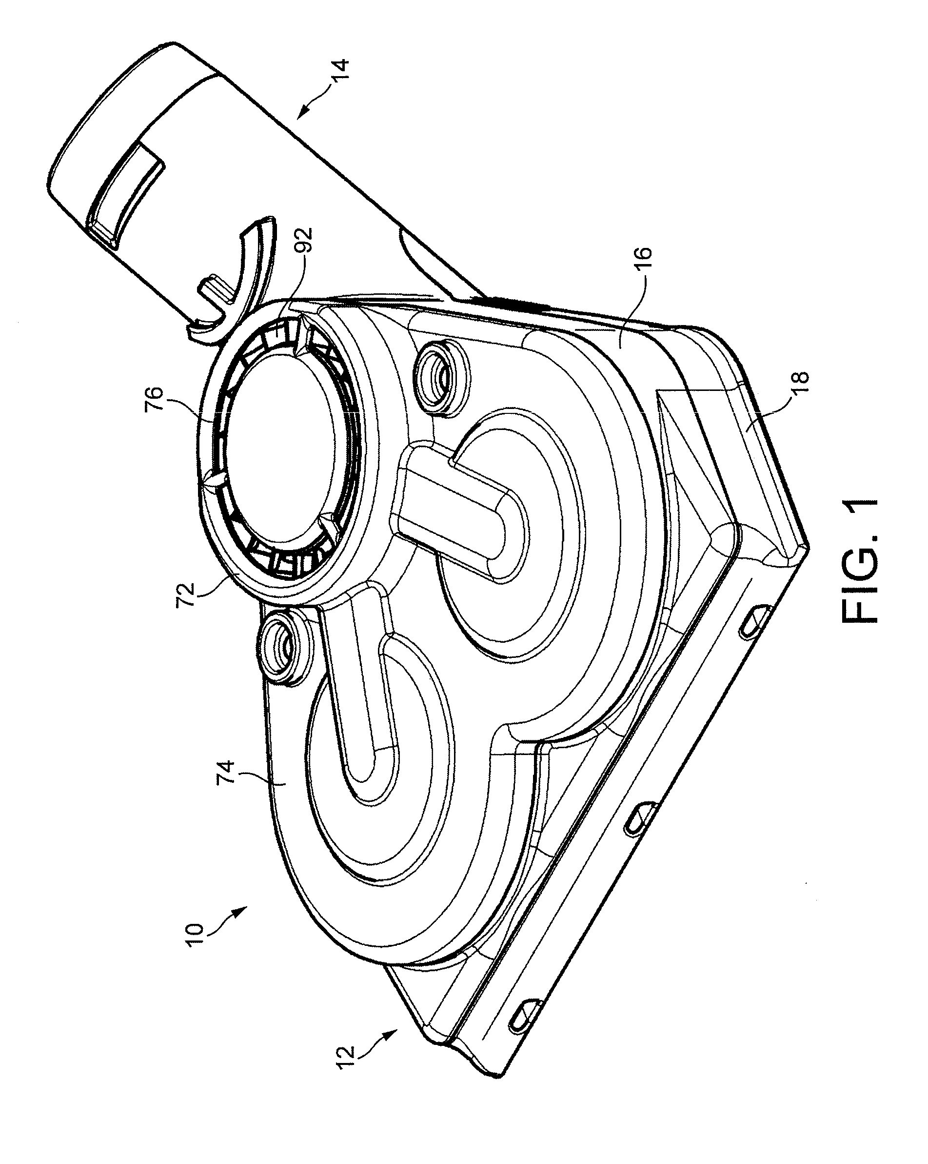
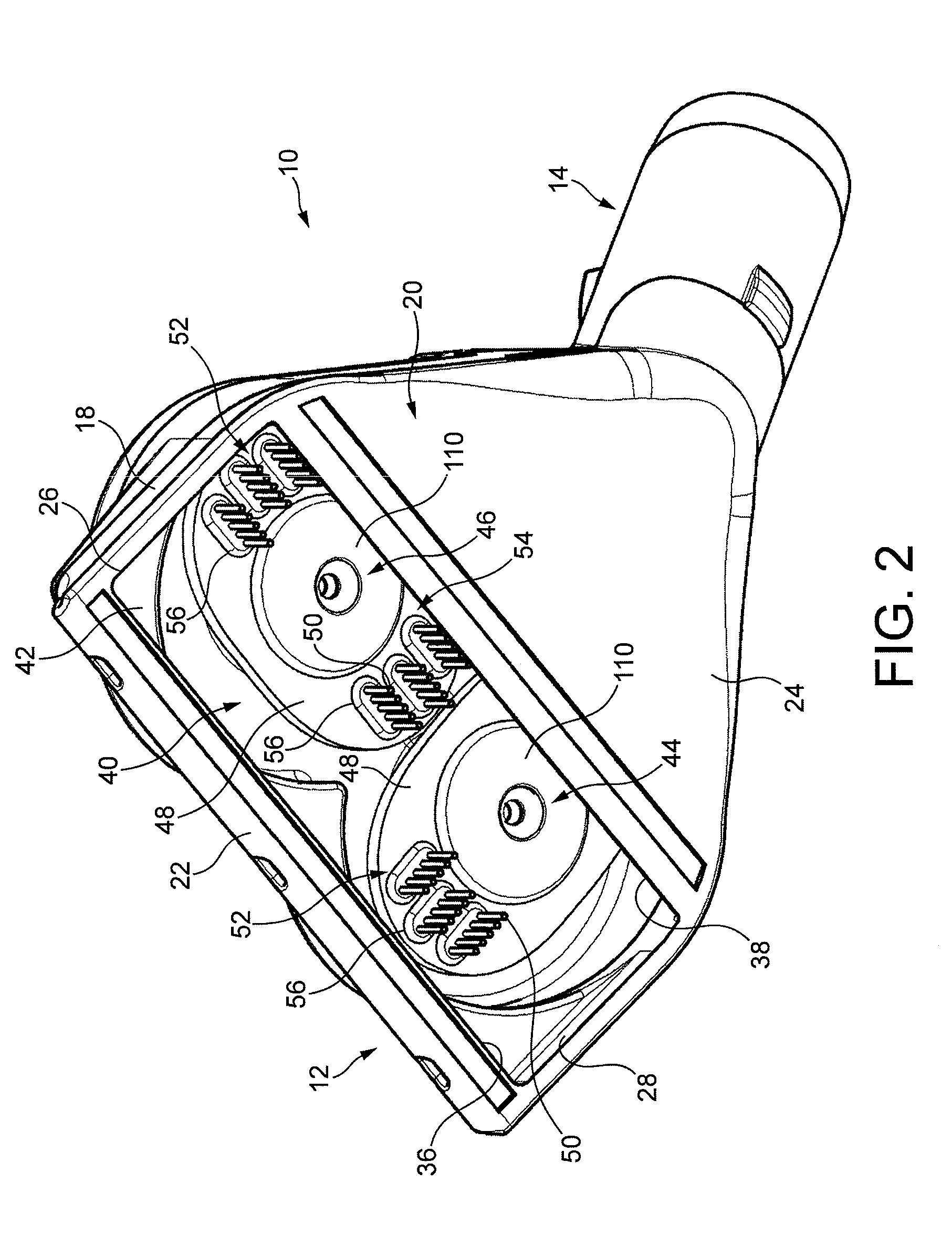
[0071]FIGS. 1 to 7 illustrate external views of a cleaner head 10 for a vacuum cleaning appliance. In this embodiment, the cleaner head 10 is arranged to be connectable to a wand or hose of a cylinder vacuum cleaning appliance. The cleaner head 10 comprises a main body 12 and a conduit 14 connected to the main body 12. The main body 12 comprises an upper body section 16 and a lower body section, or sole plate, 18 connected to the upper body section 16. In this example, the conduit 14 is integral with the upper body section 16, but it may be connected to the upper body section 16, for example by welding or using an adhesive. The conduit 14 is connectable to a wand of a hose and wand assembly of the vacuum cleaning appliance (not shown). The vacuum cleaning appliance comprises a fan assembly for drawing an air flow through the cleaner head. The sole plate 18 may be removable from the upper body section 16 of the main body 12.

[0072]The sole plate 18 comprises a bottom surface 20 which,...


PUM


Abstract

A cleaner head for a vacuum cleaning appliance includes a first rotatable agitator and a second rotatable agitator for sweeping debris from a surface, each agitator comprising a disc-shaped body and a plurality of resilient members, preferably in the form of bristles, mounted on the body for engaging the surface. The agitators are housed within an agitator chamber which includes a downwardly-directed opening through which debris energized by the bristles enters the cleaner head. The opening is located in a plane, and each body is inclined relative to the plane of the opening so that, with rotation of the agitator, the bristles protrude through the opening. The bristles of the first agitator are angularly offset from the bristles of the second agitator.

Description

REFERENCE TO RELATED APPLICATIONS[0001]This application claims the priority of United Kingdom Application Nos. 1021200.9 and 1021198.5, filed Dec. 14, 2010, the entire contents of which are incorporated herein by reference.FIELD OF THE INVENTION[0002]The present invention relates to a cleaner head for a cleaning appliance. In a preferred embodiment, the cleaner head is suitable for use with a vacuum cleaning appliance.BACKGROUND OF THE INVENTION[0003]A vacuum cleaner typically comprises a main body containing dirt and dust separating apparatus, a cleaner head connected to the main body and having a suction opening, and a motor-driven fan unit for drawing dirt-bearing air through the suction opening and the cleaner head, and into the main body. The suction opening is directed downwardly to face the floor surface to be cleaned. The dirt-bearing air is conveyed to the separating apparatus so that dirt and dust can be separated from the air before the air is expelled to the atmosphere. ...

Claims


Application Information

Patent Timeline
Patent Type & Authority Applications(United States)
IPC IPC(8): A47L9/04
CPCA47L9/0472A46D1/0207A47L9/04
Inventor FORBES, STEVEN JOHNARTHEY, SPENCER JAMES ROBERTILES, JEAN-PAUL MARK
Owner DYSON TECH LTD
Why Eureka
Try Eureka