
Arrangement for axial securing of grooved bolt

a technology of grooved bolts and axial securing, which is applied in the direction of couplings, machine supports, manufacturing tools, etc., can solve the problems that the retaining force of the clip and the spring force of the tongue cannot be chosen arbitrarily or independently of each other, and achieve the effect of reliable arrangement and minimal siz

Active Publication Date: 2007-02-08
KONECRANES GLOBAL
View PDF16 Cites 18 Cited by
  • Summary
  • Abstract
  • Description
  • Claims
  • Application Information

AI Technical Summary

Benefits of technology

The present invention provides a reliable and cost-effective arrangement for securing a grooved bolt using a holding element and a securing element. The holding element has an opening through which the bolt passes in the axial direction and the securing element engages the bolt in the axial direction and secures it in the locked position. The securing element may be easily pressed into and out of the groove and does not require costly machining. The holding element protects the securing element from accidental loosening or unintended movement. The holding element may be a U-shaped metal plate or guide straps. The securing element may move between the legs of the holding element or from one end to the other. The holding element may have a recess in the curve between the two legs to hold the securing element securely. The invention provides a simple and effective solution for securing a grooved bolt.

Problems solved by technology

Often, the clips become bent or deformed during this process.
Because these clamps are punched out and bent into shape from a single metal sheet, the retaining force of the clip and the spring force of the tongues may not be chosen arbitrarily or independently of each other.

Method used


Image

  • Arrangement for axial securing of grooved bolt
  • Arrangement for axial securing of grooved bolt
  • Arrangement for axial securing of grooved bolt

Examples


Embodiment Construction

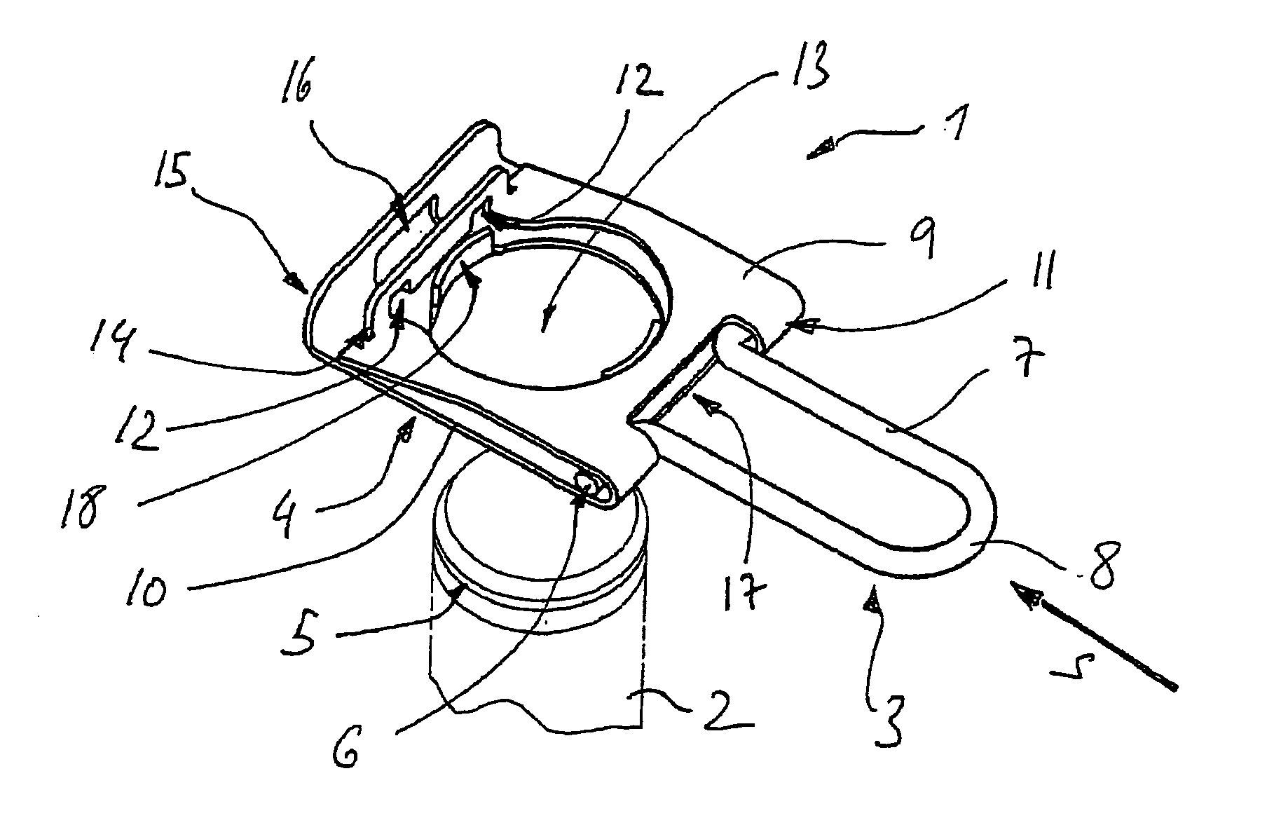
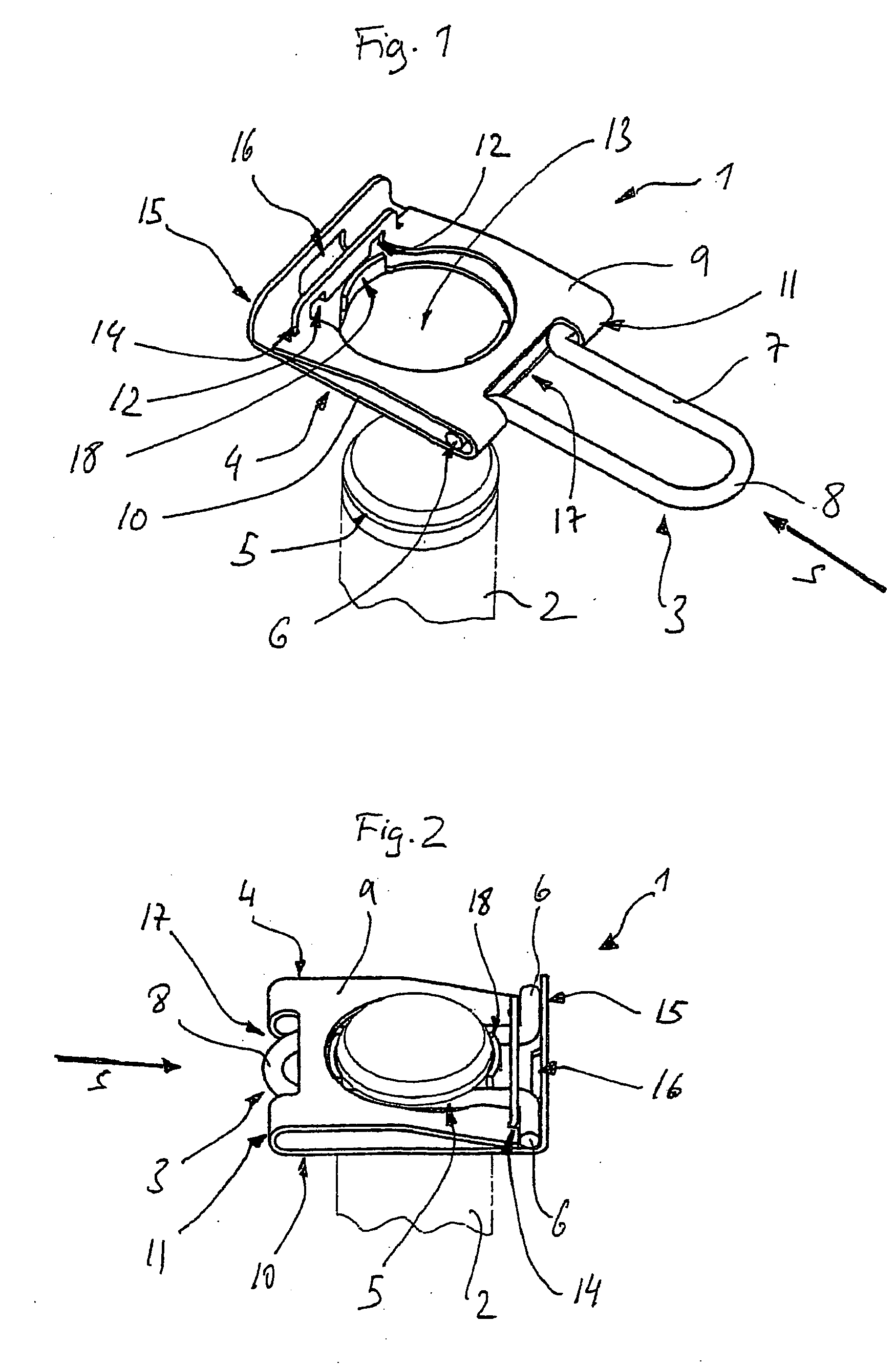
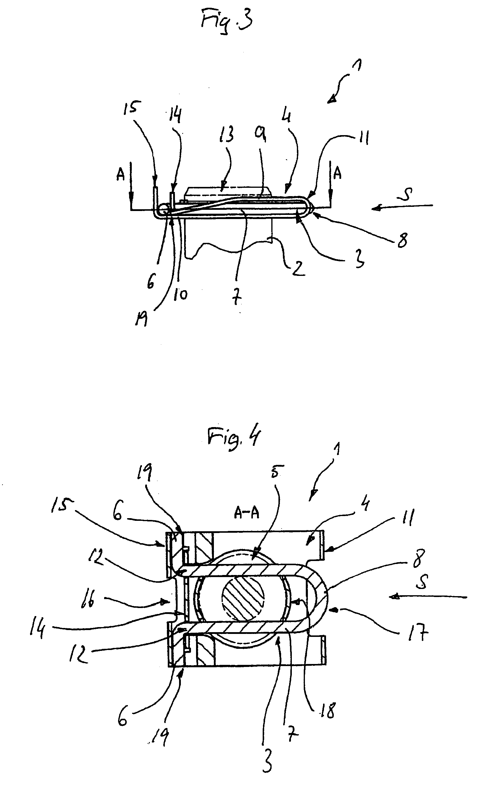
[0041] Referring now to the drawings and the embodiments illustrated therein, the overall arrangement 1, 101, 201, 301 for axial locking of a bolt 2, 102, 202, 302 or the like, provided with a groove 5, 105, 205, 305, i.e., a bolt retention, is shown in FIGS. 1-16. The arrangement or bolt retention 1, 101, 201, 301 comprises a securing element 3, 103, 203, 303, which may be configured as a locking clip that moves from an open position to a locked position relative to a holding element 4, 104, 204, 304. In the locked position, securing element 3, 103, 203, 303 engages groove 5, 105, 205, 305 and is at least partially enclosed by holding element 4, 104, 204, 304, which may be configured as a U-shaped metal plate and may be movably connected to securing element 3, 103, 203, 303.

[0042] As shown in FIGS. 1-4, bolt retention 1 includes securing element 3, which comprises a steel wire. Securing element 3 corresponds to groove 5 and has a generally U-shaped form. Securing element 3 include...


PUM


Abstract

An arrangement for axial securing of a grooved bolt includes a holding element and a securing element. The grooved bolt passes through the holding element in the axial direction. The securing element, which may be connected to the holding element, engages the groove of the bolt and secures the bolt in a locked position.

Description

FIELD OF THE INVENTION [0001] The present invention relates generally to bolt retention arrangements. BACKGROUND OF THE INVENTION [0002] Devices such as bolt retentions are familiar in many different forms. One version is a securing clip, which is pressed into a groove of a bolt to achieve a clamping effect. For example, such a clip is shown in DE 37 04 650 C2. In DE 37 04 650 C2, to achieve a clamping retention, the spring force provided by the clip is overcome when the clip is inserted into the groove. Similarly, the spring force must again be overcome to remove the clip. Often, the clips become bent or deformed during this process. [0003] Securing clamps, such as those of DE 80 19 658 U1, are also known. Besides having a U-shaped clip or plate inserted into a groove of a bolt, these clamps have a securing element that includes two tongues curved toward each other, which encircle the bolt in the locked position. The clamping effect of the tongues holds the U-shaped clip in the loc...

Claims


Application Information

Patent Timeline
Patent Type & Authority Applications(United States)
IPC IPC(8): F16M13/00
CPCF16B21/183Y10T403/58Y10T403/60F16B2200/69
Inventor FITZLER, STEFANMULLER, SVENBIRKIGT, REINHARDGERSEMSKY, UDO
Owner KONECRANES GLOBAL
Learn More