Method and apparatus for heating plastics by means of laser beams

a laser beam and plastic heating technology, applied in laser beam welding apparatus, lamination, instruments, etc., can solve the problems of inability to apply methods, high space requirements, and relatively high costs, and achieve the effect of convenient handling

Inactive Publication Date: 2007-05-29
LEISTER TECHNOLOGIES
View PDF7 Cites 27 Cited by
  • Summary
  • Abstract
  • Description
  • Claims
  • Application Information

AI Technical Summary

Benefits of technology

[0008]The invention therefore offers the possibility of implementing minimum spatial splitting of the laser beam within an optical system. It is easy to adjust the distance of the splitting onto the focal plane. This solution can be integrated in a processing head, and therefore has a minimum overall size and enjoys full flexibility of movement. Since only one optical component is responsible for splitting the light, it is possible here to switch optically between single, double or multiple radiation. The split light beams run, as it were, along the same optical axis, and so the geometrical arrangement can be implemented with minimum adjustment.
[0010]In order to produce parallel zigzag welding lines, such as are required for welding films, in particular, in accordance with a further design of the invention laser points are produced via two deflecting elements that can be moved transverse to the beam path. The deflecting elements are preferably designed in a fashion deflecting in opposite directions by a prescribed angle, and are brought into the beam path alternately. By accommodating the arrangement in a processing head, in particular in combination with a transparent ball running on the plastics material to be welded, it is possible to implement an element that is easy to handle and with the aid of which it is possible to heat and weld along virtually any desired contours.

Problems solved by technology

The space requirement and the costs are, however, relatively high, since each optical output requires all the lens components in order to shape the beam appropriately and to collimate it.
This method cannot be applied, above all, when an easy spatial splitting of the light is involved.

Method used


Image

  • Method and apparatus for heating plastics by means of laser beams
  • Method and apparatus for heating plastics by means of laser beams
  • Method and apparatus for heating plastics by means of laser beams

Examples


Embodiment Construction

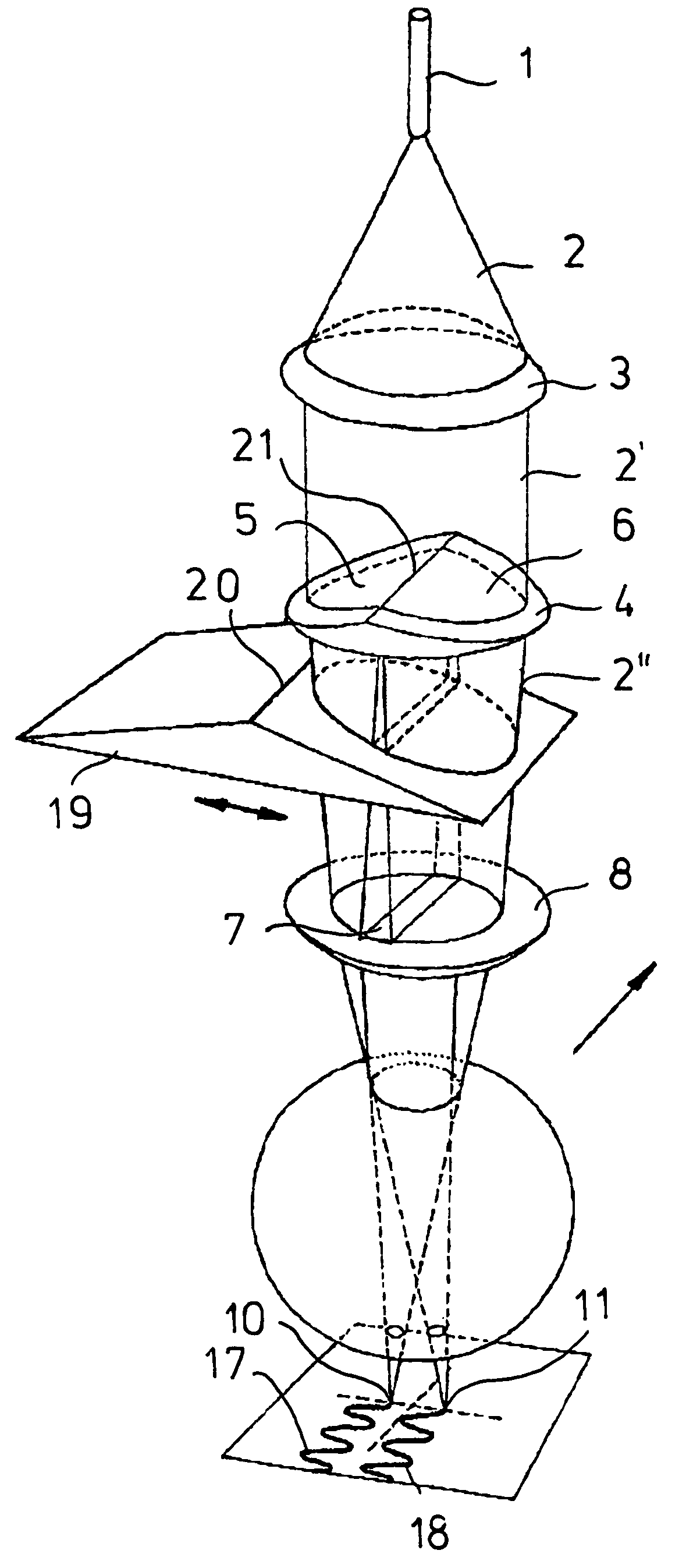
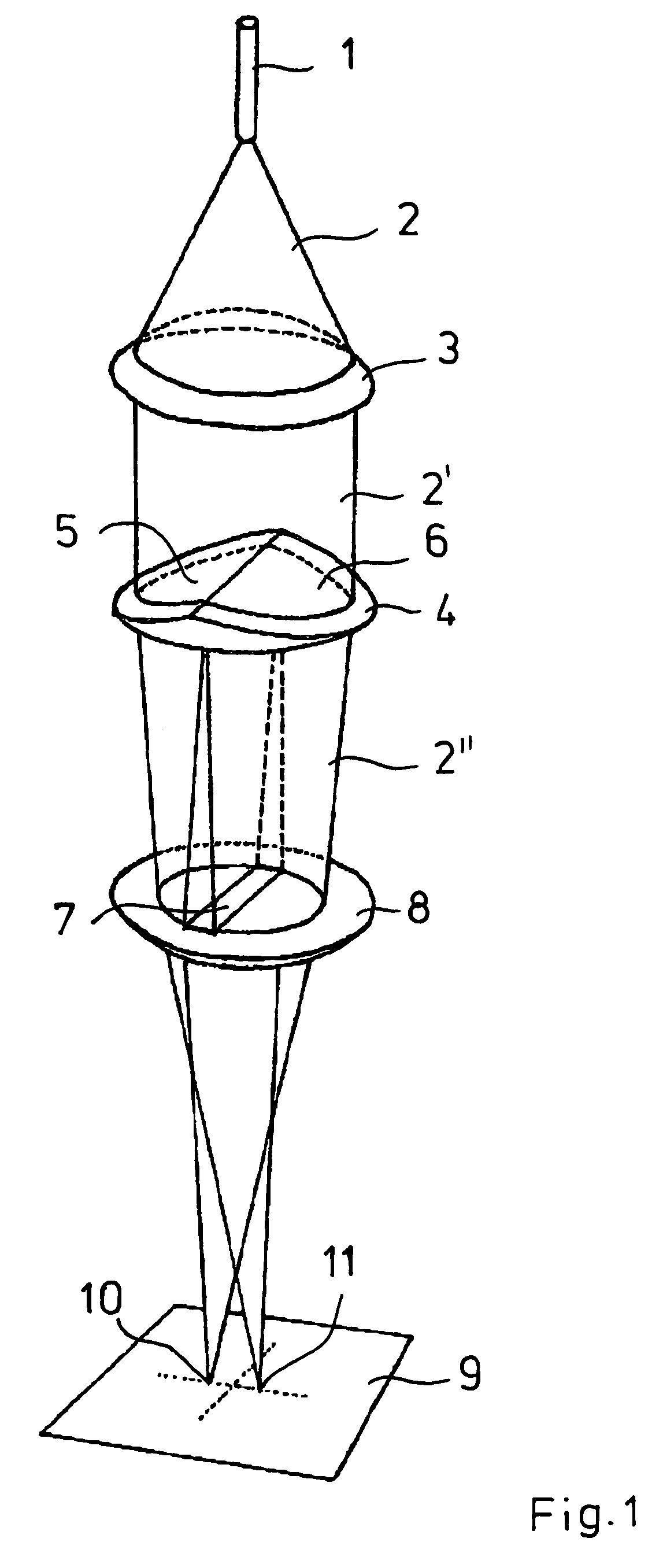
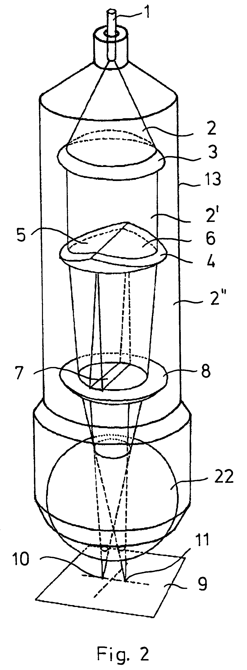
[0019]FIG. 1 shows an optical fiber 1 from which a laser beam 2 emerges. A lens 3 collimates the laser beam, which then strikes a double wedge plate 4. As is to be gathered from the figure, the wedges 5, 6 are arranged in such a way that the plane facing the collimated laser beam 2′ drops outward from the middle, and therefore the laser beam is slightly deflected toward the central optical axis. This is illustrated in the figure by the overlapping region 7 on the subsequent lens 8. The double wedge plate acts like two prisms arranged one against another which slightly deflect the laser beam along the light propagation direction. The radiation is split into two parts 2″, but still remains collimated, although it runs on in two different propagation directions. The converging lens 8 refocuses the two split rays onto a focal plane 9, where they are formed as two light points 10, 11. The wedge angle and the optical properties of the converging lens determine the distance between the two...


PUM

PropertyMeasurementUnit
angleaaaaaaaaaa
transparentaaaaaaaaaa
sizeaaaaaaaaaa

Abstract

Method and apparatus for heating plastic by laser beams with the aid of a number of laser points on the focal plane, the laser points being produced by an optical arrangement with the aid of a multiple wedge plate. The arrangement can be integrated in a processing head.

Description

BACKGROUND OF THE INVENTION[0001]The present invention relates to a method for heating plastics by means of laser points from a laser beam on a focal plane, preferably for welding plastics using the laser transmission method. The invention also relates to an apparatus for heating plastics by means of laser beams with the aid of a processing head for accommodating devices for shaping the laser beam.[0002]In order to weld plastics by means of laser beams, it is known in the so-called transmission welding method for a first plastic part that is transparent to the laser beam to be heated at the contact surface with a second plastic part that is absorbent for the laser beam, and for these parts to be welded to one another under the action of pressure. In order to achieve the desired speed at which the laser is moved over the plastic components and, nevertheless, to ensure good welding qualities, it is necessary to install in the beam path a preheating process that ensures that the heatin...

Claims


Application Information

Patent Timeline
Patent Type & Authority Patents(United States)
IPC IPC(8): B29C65/16B23K26/06B23K26/067B23K26/08B23K26/20B23K26/24B29C65/00
CPCB23K26/0604B29C66/9161B23K26/067B23K26/246B29C65/1635B29C65/1658B29C65/1687B29C66/024B29C66/1122B29C66/20B29C66/221B29C66/223B29C66/232B29C66/43B29C66/80B29C66/81267B29C66/83441B29C66/836B29C66/8362B29C66/90B29C66/9192B23K26/0608B29C66/91411B29C65/1664B29C65/1654B29C65/00B29C66/0242B29C66/21B29K2313/00B29K2909/08B29C65/1638B29C65/16B23K26/244B29K2995/0027B29C66/8122
Inventor CHEN, JIE WEI
Owner LEISTER TECHNOLOGIES
Why Eureka
Try Eureka