
Compact wallet

a wallet and compact technology, applied in the field of wallets, can solve the problems of not being able to bend or electronic snoop, not being able to carry cash, etc., and achieve the effects of reducing the size of the plate, and maximizing the expansion of the interior volum

Active Publication Date: 2020-10-06
RIDGE WALLET LLC
View PDF25 Cites 27 Cited by
  • Summary
  • Abstract
  • Description
  • Claims
  • Application Information

AI Technical Summary

Benefits of technology

[0007]The present invention utilizes bookend plates resiliently bound with an encircling elastic band to contain one or more credit card-sized objects in a wallet configuration. A novel feature maximizes the expansion of interior volume by allowing the strap to expand along a maximum length afforded by a longitudinal dimension of the wallet while avoiding anchor points which would effectively shorten the length. Another novel feature achieves minimal sizing of the plates by channeling the strap with interior means rather than by means of profile extensions. Yet another novel feature achieves easy access to, and viewing of, the contents through a cut-away feature which allows the contents to be partially pushed up where a fulcrum is provided for pinching the plates together and fanning out the contents.
[0008]It is, therefore, an object of the invention to provide a compact wallet substantially no larger than a credit card. It is a further object to maximize expandability of the wallet to accommodate multiple objects of substantially the same size. It is a further object to protect the contents of the wallet from damage or loss by open-ended drop through. It is a further object to facilitate selection of any one object from the bound group. It is a further object to accommodate folded currency handily on the outside of the wallet. It is a further object to present essentially smooth contours for snag-free passage into and out of pockets of clothing or bags. It is a further object to provide means and method for changing out elastic bounding bands. It is a further object to provide a method for making a compact wallet with different features attached thereto which can be modularly exchanged.
[0009]These objects, and others to become hereinafter apparent, are embodied in a compact wallet comprising, in a first element, at least two rigid plates interposed to sandwich card-like contents there between, each rigid plate having a longitudinal extent. A second element is at least one encircling elastic band interposed with the at least two rigid plates, over the longitudinal extents thereof, to bias them inwardly and securely hold the card-like contents while providing elastic volume between the plates for adding additional contents. A third element is a channeling means configured to minimize the profile of the wallet and hold position of the at least one encircling elastic band with respect to each rigid plate. The channeling means additionally allows freedom for the dynamic extension and contraction of the band over the entire running length of the band. With such means and in such manner, card-like contents may be carried with minimal silhouette on or with a person while allowing expandable capacity and ready access to individual contents from between the at least two rigid plates.

Problems solved by technology

Such a traditional wallet, with its internal sleeves, compartments, and windows, not to mention contents, can bulge uncomfortably or telltale-like from clothing, or inconveniently in a handbag, while giving little protection from moisture, bending or electronic snooping.
Carrying cash, except for an emergency bill or two, has increasingly become both unnecessary and inconvenient in consideration of the nuisance in making change and risk of loss through theft or carelessness.
In most cases, the running length of the strapping is limited by the distance between fixture locations on the plates, which limits the expansion capability and, therefore, the capacity for contents.
In other cases, it becomes difficult to view the stored contents without moving them all.
In other cases, selectively withdrawing of just one of the contents, particularly with a presentation of the shorter edge, is frustrated by the compaction applied.
In other cases, the plates are of insufficient rigidity to protect the contents from bending.

Method used


Image

  • Compact wallet
  • Compact wallet
  • Compact wallet

Examples


Embodiment Construction

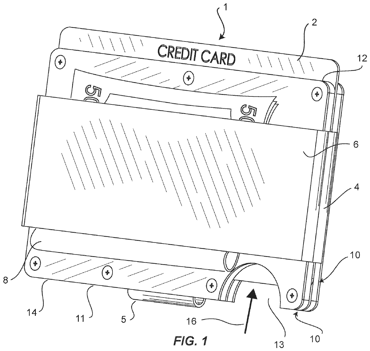
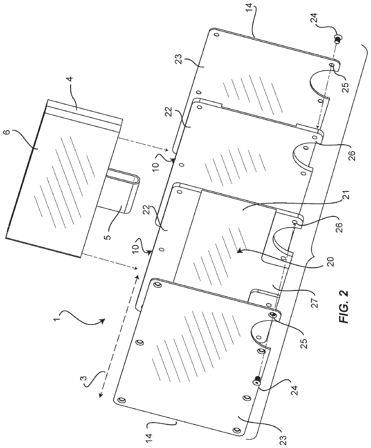
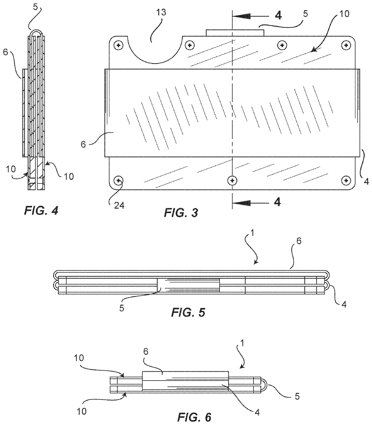
[0027]Referring to FIGS. 1 and 2, a compact wallet 1 is comprised of at least two rigid plates 10, serving as “bookends” as it were, with one or more card-like contents 2 sandwiched between them. The sandwiched composite is bound by at least one encircling elastic band 4. The encircling elastic band 4 holds the card-like contents 2 securely by means of compression, while also expanding elastically to open space between the rigid plates 10. The added volume of the space provides capacity for additional contents. The rigid plates 10 are sized to the dimensions of a standard credit card and the resulting perimeter defines a profile 14. A channeling means 20 prevents the encircling elastic band 4 from adding more than negligible breadth to profile 14. This profile minimization is accomplished by locating the channeling means 20 internally to the rigid plates 10. In other words, no structures projecting from the profile 14 are needed to fixture the encircling band 4, as in the case of pr...


PUM


Abstract

The present invention is a compact wallet designed to present a minimal silhouette in a shirt, pants or purse pocket. Novel features hold the silhouette to the minimal dimensions of a credit card while affording maximal expandability for content storage and accessibility. A novel method makes additional features modularly available.

Description

CROSS-REFERENCE TO RELATED APPLICATIONS[0001]This is a Continuation-In-Part Application claiming priority to parent U.S. Non-Provisional patent application Ser. No. 14 / 706,019, filed May 7, 2015, and to International Application PCT / US16 / 31472, filed May 9, 2016, both of which are incorporated herein in entirety.FIELD OF THE INVENTION[0002]This invention relates to billfold wallets, and more particularly to low-profile wallets for credit cards.BACKGROUND OF THE INVENTION[0003]Who among us would not prefer a wallet minimally-sized to just the stack of credit cards carried in the typical bi- or tri-fold leather wallet? Such a minimalist wallet could be easily slipped into a shirt pocket, or present a slim profile in a pants pocket or purse. Even with money clipped to it, the bulk of such a wallet would be less than that of the fold-over-envelope-type-wallet traditionally used to carry cards, money and identification. Such a traditional wallet, with its internal sleeves, compartments, ...

Claims


Application Information

Patent Timeline
Patent Type & Authority Patents(United States)
IPC IPC(8): A45C1/06A45C13/18A45C1/08A45C11/18
CPCA45C13/185A45C1/08A45C1/06A45C11/182A45C2011/186A45C2001/065A45C2001/083A45C2001/062
Inventor KANE, DANIEL
Owner RIDGE WALLET LLC
Learn More