
Apparatus for converting wind into circular mechanical motion

a technology of mechanical motion and apparatus, which is applied in wind motors, renewable energy generation, greenhouse gas reduction, etc., can solve problems such as the maximum size of openings, and achieve the effect of promoting sail billowing and minimizing wind spillag

Active Publication Date: 2017-06-27
SUETRONG NICHOLAS ARUHN AYLOR +1
View PDF13 Cites 0 Cited by
  • Summary
  • Abstract
  • Description
  • Claims
  • Application Information

AI Technical Summary

Benefits of technology

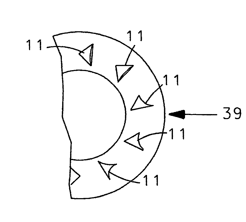
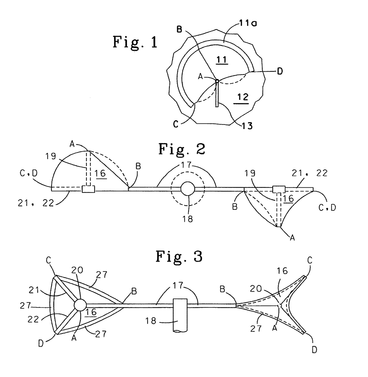
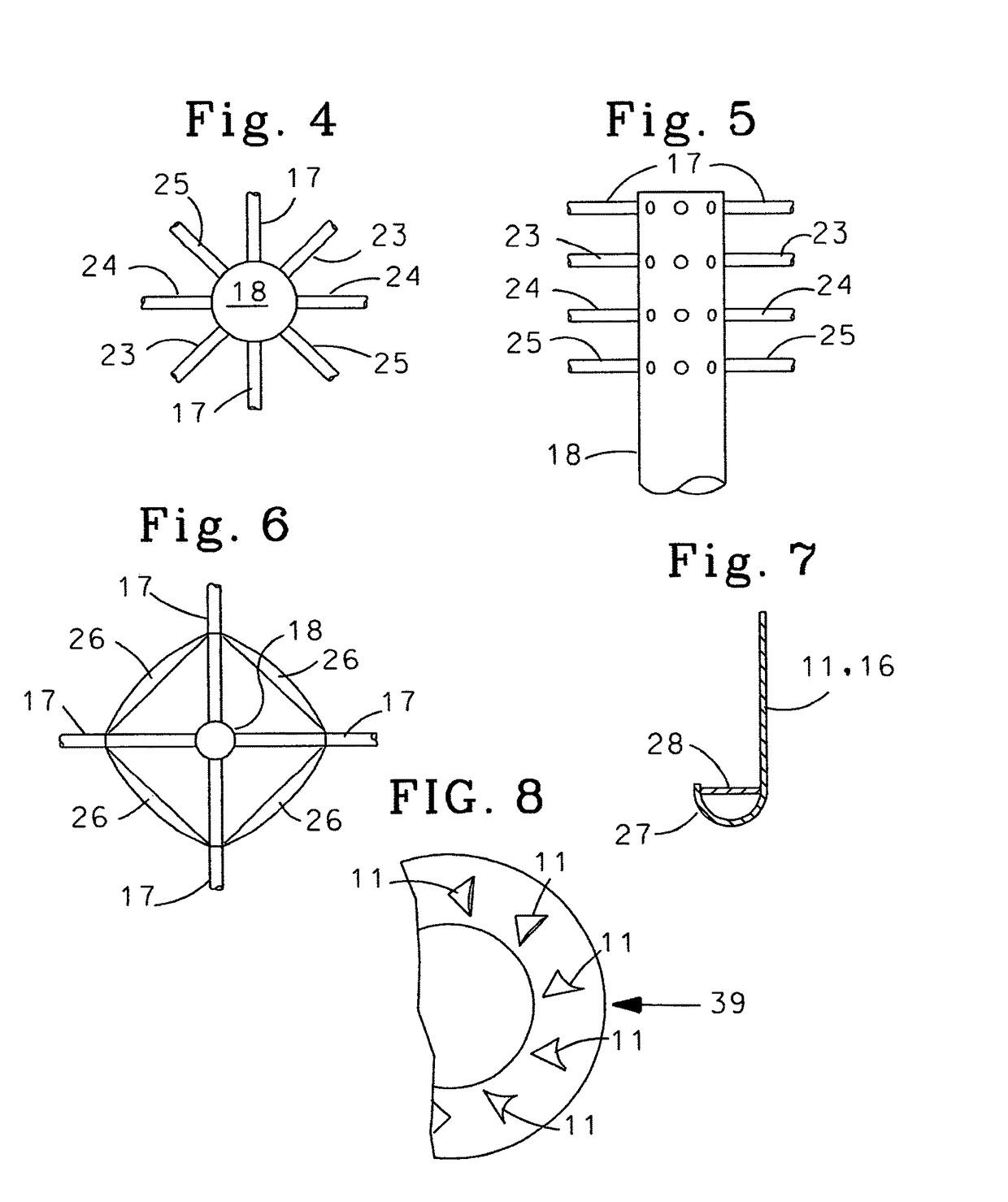
The present invention provides flexible sail structures with large differences in wind resistance when the wind is coming from opposite sides of the structure. The sails are of two types: pocket-like and cup-like. The pocket-like sail is attached to a rotating structure so that the rotating structure forms part of the pocket, and the open edge of the pocket-like sail is attached to a spar structure to keep the pocket-like sail partially open even when the wind is coming from the back of the pocket. The cup-like sail is attached to a rotating structure at or near the outside rim to maximize the ability of the sail to rotate the structure. The center spars of the sails act to help maximize expansion of both the pocket-like and cup-like sails when they are filled with wind. The sails are attached to various rotating structures close to, or on, the outside edge of the rotating structures. The sails can also have open "cuffs" on the inside edges to help minimize spillage of wind and to promote the billowing of the sails when wind enters them.

Problems solved by technology

As a result, this causes the maximization of the size of the opening when the wind (air) fills the sail.

Method used


Image

  • Apparatus for converting wind into circular mechanical motion
  • Apparatus for converting wind into circular mechanical motion
  • Apparatus for converting wind into circular mechanical motion

Examples


specific embodiments

[0058]Decorative Structures

[0059]The rotating structures can be used to provide visual interest for decorative purposes as shown in FIG. 9. Such structures are similar to, but more interesting than, the common pinwheels seen on many lawns. Examples of such lawn ornaments are found in U.S. Pat. No. 5,092,809, Kessler et al., issued Mar. 3, 1992 and U.S. Pat. No. 6,789,911, Nelson et al., issued Sep. 14, 2004, said patents being incorporated herein by reference.

[0060]The structures can include cylinders with the pocket type of sail structures attached around the cylinders to create motion when the wind blows and the cup-like sails which are either decorated or which are used to move decorative structures around when the wind blows. Since the structures can have the sails oriented either to provide clockwise or counter clockwise rotation, the structures can be “stacked” as shown in FIG. 9, on top of each other to provide additional visual interest with one structure in the stack rotati...


PUM


Abstract

Pocket and cup sails formed from flexible materials, especially such sails formed with excess material, have spar like supports attached at their deepest point to maintain the depth of the said sails when the wind fills them so that the sails expand to maximize resistance to the wind coming into the openings of the sails and so that the sails deflate when the wind is coming from the back of the sails to minimize resistance to the wind, the said sails being attached to rotor arms on rotary devices to provide torque, the torque being used to rotate decorative structures including the sails themselves, generate electricity, bring airplane tires up to speed before landing, and / or measure wind speed, and sails optionally having cuffs on the inside to help the sails inflate and / or maintain inflation by minimizing spillage of air.

Description

[0001]This is a division of our commonly titled, copending, application Ser. No. 13 / 815,811, filed Mar. 16, 2013 from which we claim priority.BACKGROUND OF THE INVENTION[0002]Field of the Invention[0003]This invention relates to improvements in converting air movement into rotary mechanical action. The invention has utility in several areas including: creating rotating visual objects that are decorative; creating rotary motion that can be used to create electricity by rotating one or more of the elements of an electricity generator; and increasing the rotational speed of airplane wheels before they touch the ground to avoid excessive wear on the tread that occurs when the initial contact with the ground increases the speed of the wheel to match the speed of the airplane.[0004]Description of Related Art[0005]There have been many attempts to convert wind energy into electric energy using various configurations. It is desirable to have a rotation around a vertical axis where the device...

Claims


Application Information

Patent Timeline
Patent Type & Authority Patents(United States)
IPC IPC(8): F03D3/06F03D3/00F03D9/25
CPCF03D3/067F03D3/002F03D3/005F03D9/25F05B2240/311Y02E10/74
Inventor SUETRONG, NICHOLAS ARUHN AYLORAYLOR, ROBERT BENSON
Owner SUETRONG NICHOLAS ARUHN AYLOR
Learn More