Retrofittable reinforced door jamb plate

Inactive Publication Date: 2007-02-08
GATRELL QUINN B
View PDF9 Cites 5 Cited by
  • Summary
  • Abstract
  • Description
  • Claims
  • Application Information

AI Technical Summary

Benefits of technology

[0008] In another aspect of the invention, it provides a retrofittable reinforced door jamb plate that can be easily and inexpensively manufactured.
[0009] In still another asp

Problems solved by technology

In addition, the hinges on an exterior door can be a weak point.
If the hinges are subjected to force by someone trying to gain entry to the premises, the screws are likely to pull free causing the hinges to fail and permitting unauthorized entry.
While this may slow

Method used


Image

  • Retrofittable reinforced door jamb plate
  • Retrofittable reinforced door jamb plate
  • Retrofittable reinforced door jamb plate

Examples


Example

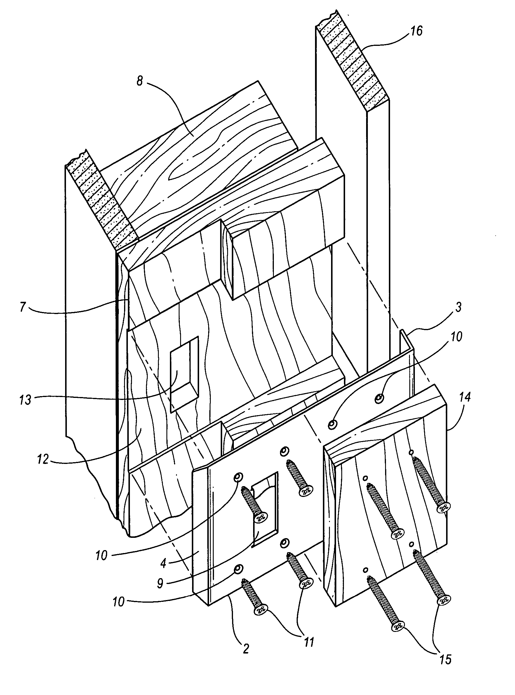
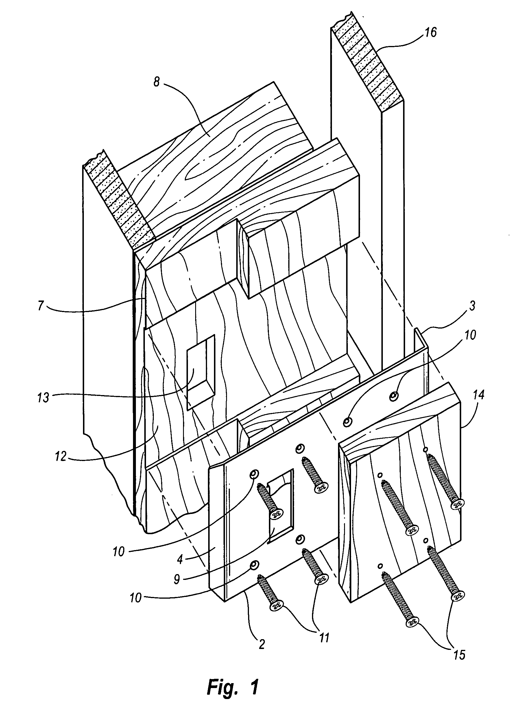
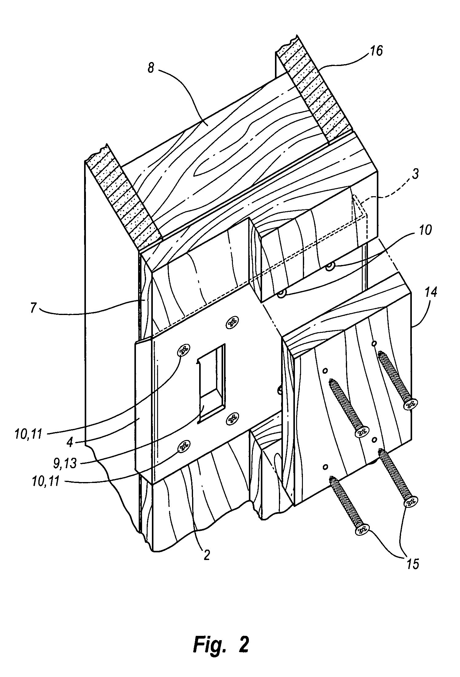
[0022] The retrofittable reinforced doorjamb plate of this invention is shown in three views in FIGS. 1-3, 5B and 5C. The plate is a piece of hard, tough material, preferably steel. The reinforced plate 1 is comprised of at least two legs, a long leg 2 extending the width of the doorjamb and a shorter leg 3 that is perpendicularly attached to long leg 2 and extends toward the door frame on the exterior edge of the door jamb. Additional legs 5 and 6 that extend off of leg 3 into the door jamb 7 or door frame 8 may also be included on the plate as is shown in FIGS. 5B and 5C. The reinforced plate may also include a plate lip 4 when it is used in conjunction with a door latch assembly. When the reinforced plate is used in conjunction with a dead bolt or hinge, no such lip is included as shown in FIGS. 4, 5D and 7. Plate 1 contains at least one aperture 9 that permits a door latch or deadbolt to be secured through the plate into latch hole 13. Plate 1 may also contain additional apertur...


PUM


Abstract

A retrofittable reinforced doorjamb plate extending along the facing side of a door jamb. Installation of the reinforced door jamb plate requires any potential intruder to use enough force to drive the reinforced door jamb plate through the entire width of the door jamb. The reinforced doorjamb plate can be easily installed on an existing doorjamb and easily manufactured, but not easily defeated by an intruder.

Description

FIELD OF THE INVENTION [0001] The present invention relates generally to door security devices, more specifically to a method and apparatus for retrofittably reinforcing a door jamb to prevent forcible entry into a residence or business. BACKGROUND OF THE INVENTION [0002] Usually, exterior doors on a residence or business are secured in the closed position through the use of a latch mechanism that includes a doorknob and / or a deadbolt lock on one edge of the door and a hinge mechanism on the opposite side of the door. The door jamb, which is attached to the door frame, receives a portion of the latch mechanism and / or deadbolt lock when the door is in the closed and locked position. Typically, the door handle lock and deadbolt lock recess into striker plates that are attached to the door jamb by screws. [0003] The weakest areas of the secured exterior door are where the latch mechanism and dead bolt lock recess into the door jamb. Even the strongest door lock or deadbolt is only as s...

Claims


Application Information

Patent Timeline
IPC IPC(8): E05B15/02
CPCE05B15/0205Y10T292/68
Inventor GATRELL, QUINN B.
Owner GATRELL QUINN B
Why Eureka
Try Eureka