Multifrequency H-shaped antenna

a multi-frequency, h-shaped technology, applied in the direction of elongated active element feed, resonant antenna, radiating element structure, etc., can solve the problem of only transmitting and receiving in a single frequency band, and achieve the widest bandwidth and widest bandwidth of antenna

Inactive Publication Date: 2007-02-08
WISTRON NEWEB
View PDF3 Cites 41 Cited by
  • Summary
  • Abstract
  • Description
  • Claims
  • Application Information

AI Technical Summary

Problems solved by technology

The drawback of the antenna of this type is that it can transmit and receive only in a single frequency band.

Method used


Image

  • Multifrequency H-shaped antenna
  • Multifrequency H-shaped antenna
  • Multifrequency H-shaped antenna

Examples


Embodiment Construction

[0016] The detailed description of the present invention will be discussed in the following embodiments, which are not intended to limit the scope of the present invention, but can be adapted for other applications. While drawings are illustrated in details, it is appreciated that the quantity of the disclosed components may be greater or less than that disclosed, except expressly restricting the amount of the components.

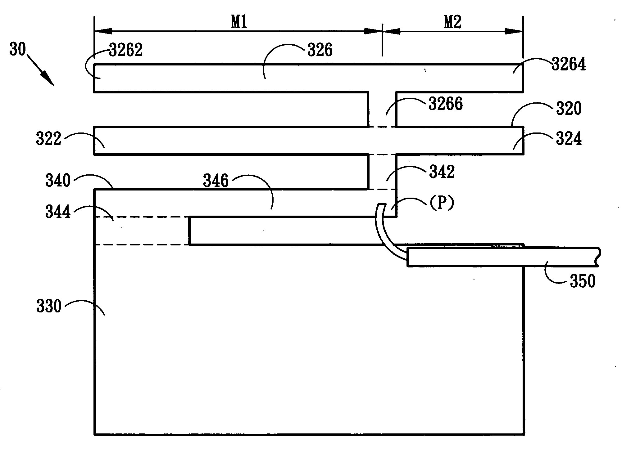
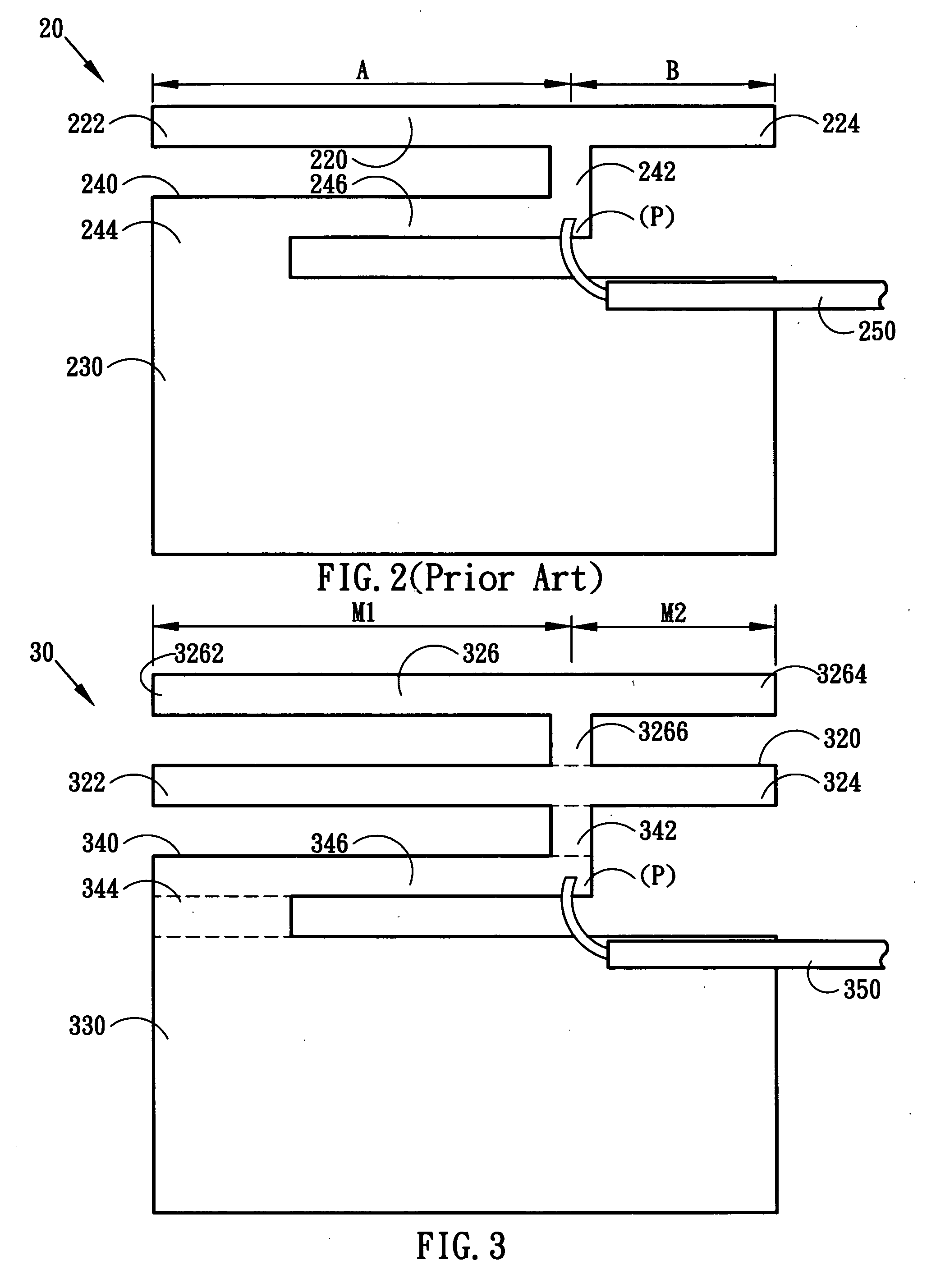
[0017]FIG. 3 illustrates a preferred embodiment of a multifrequency H-shape antenna of this invention. The antenna includes: a conductive radiating element 320 in the form of a wire that extends in a longitudinal direction and that has opposite left end 322 and right end 324, and a T construction 326 connected to the conductive radiating element 320, the T construction 326 lying on top of the left end 322 and right end 324 to achieve a wider bandwidth of the antenna, the T construction 326 having opposite left end 3262 and right end 3264, and a transmission line 32...


PUM


Abstract

A multifrequency H-shape antenna is disclosed herein. The multifrequency H-shape antenna includes a conductive radiating element, a conductive grounding element, a conductive interconnecting element, and a coaxial cable. The conductive radiating element includes a left end, a right end, and a T construction. The conductive interconnecting element includes a first part, a second part, and a third part. The conductive interconnecting element is connected between the conductive radiating element and the conductive grounding element. The coaxial cable is electrically connected to the feeding point of the conductive interconnecting element. By using the improved construction described above, the wireless bandwidth can be increased.

Description

BACKGROUND OF THE INVENTION [0001] 1. Field of the Invention [0002] The present invention generally relates to an antenna, and more particularly to a multifrequency H-shape antenna. [0003] 2. Description of the Prior Art [0004] In these years, wireless communication technologies are prevailing, and the devices built inside with a wireless communication antenna are widespread. In this fast change era, for example, the notebook computers with wireless communication function are prevailing increasingly, and the need for compact notebook computers increases gradually. Cooperating with the design of structure, the wireless communication antenna should be shrunk into the limited space. [0005]FIG. 1 illustrates a conventional Planar Inverted-F Antenna 10 (PIFA) including a rectangular conductive radiating element 12, a rectangular conductive grounding element 13, a conductive signal feeding point 14, and a conductive grounding leg 15. The conductive radiating element 12 has opposite left a...

Claims


Application Information

Patent Timeline
Patent Type & Authority Applications(United States)
IPC IPC(8): H01Q1/38H01Q5/371
CPCH01Q5/371H01Q9/42
Inventor WEI, SHEN-PIN
Owner WISTRON NEWEB
Why Eureka
Try Eureka