Method for optimizing output in ultrashort-pulse multipass laser amplifiers with selective use of a spectral filter

a laser amplifier and ultrashort pulse technology, applied in the direction of lasers, electromagnetic transmission, transmission, etc., can solve the problems of narrow gain, minor non-ideal effect of etalon or filter, and narrow gain shape, so as to improve pulse shape and increase system gain

Active Publication Date: 2007-02-08
UNIV OF COLORADO THE REGENTS OF
View PDF4 Cites 11 Cited by
  • Summary
  • Abstract
  • Description
  • Claims
  • Application Information

AI Technical Summary

Benefits of technology

[0019] This technique is particularly useful in multipass amplifiers, because the path of the beam can be directed to bypass the filter in later passes, rather than moving the filter itself. As a feature, the location of the filter can be adjusted offline in order to select how many passes are intersected by the filter and how many are bypassed. As a feature, the amplifier may be a cryogenically cooled device and the spectral filter a custom-designed designed filter that compensates for the narrowing of gain profile that occurs in cryogenic amplifiers.
[0020] The present invention uses a “multipass amplifier” configuration, wherein the pulses do not retrace exactly the same path through the laser crystal for many passes, but rather shift slightly in path with each pass until the final pass intersects a mirror, which removes the pulse from the amplifier for use as an output pulse. The filter is placed such that early passes intersect the filter, while later passes bypass it. Causing the filter to intersect the beam for the first several passes but bypass it for the final several passes increases system gain and improves pulse shape.

Problems solved by technology

Gain narrowing has long been recognized as a problem in amplifiers where the beam passes through the amplifying medium multiple times (e.g. multipass configurations and regenerative configurations).
The resulting gain shape achieved is not ideal however, as it is not flat but rather a double peak shape or “hard edges” on the spectrum.
This non-ideal effect of the etalon or filter is minor in early passes, because the gain is high and offsets the “double peak” effect of the filter.
Furthermore, the amount of gain the amplifier can achieve is degraded by use of a filter in these last few passes when the power is the highest.
However, no prior work in the field discusses the insertion of such a filter in earlier passes but not later passes, although it is the case that some laser systems have used two stages of amplification—the first of which did include the filter, and the second of which did not and others [7, 8, 9] have removed the pulse from the amplifier before a final pass through the filter.
However, no attempt was made in past work to fabricate and mount the filter in such a way that the number of passes through which the filter is inserted can be varied.

Method used


Image

  • Method for optimizing output in ultrashort-pulse multipass laser amplifiers with selective use of a spectral filter
  • Method for optimizing output in ultrashort-pulse multipass laser amplifiers with selective use of a spectral filter
  • Method for optimizing output in ultrashort-pulse multipass laser amplifiers with selective use of a spectral filter

Examples


Embodiment Construction

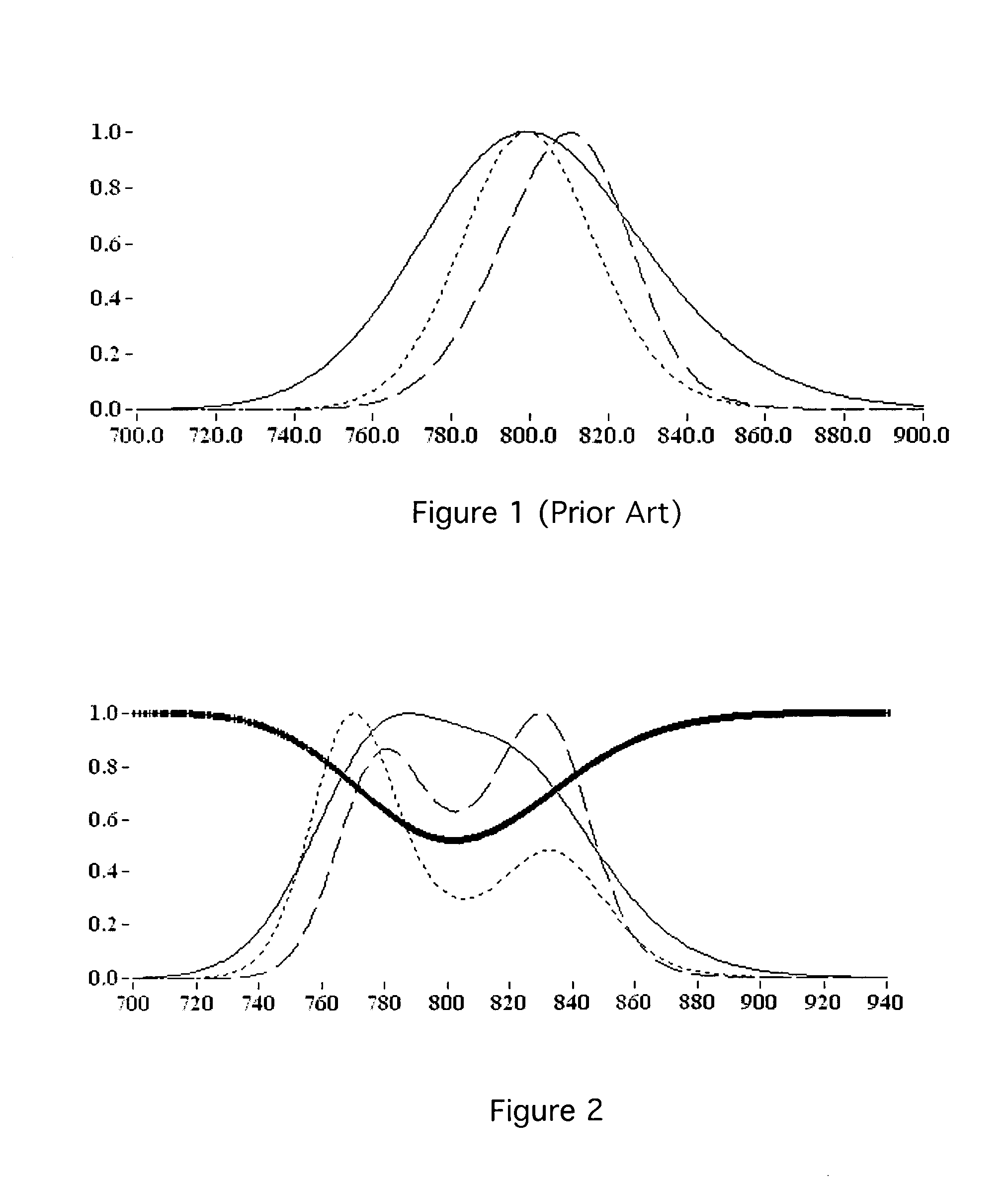
[0032]FIG. 1 (Prior Art) is a plot showing the effect of multiple passes of a pulse on pulse spectrum in a ti:sapphire amplifier system without a gain flattening filter. The plot shows standard gain shaping / narrowing in a Ti:sapphire laser amplifier at room temperature (300 K). The solid curve is the input spectrum from the oscillator, the short dashed line is the spectrum after seven passes in the amplifier, and the long dashed is output spectrum from amplifier, after twelve passes. The spectrum after seven passes exhibits gain narrowing but little spectral pulling because it is not extracting significant energy, yet (it is below saturation), and therefore the red end of the spectrum (temporally the first wavelengths to see the gain as the pulse goes through the gain media) is not “stealing” gain from the blue (trailing) end of the spectrum. The spectrum after 12 passes shows a significant red shift compared with 7 passes, due to the combined action of gain saturation with positive...


PUM


Abstract

A method for optimizing multipass laser amplifier output utilizes a spectral filter in early passes but not in later passes. The pulses shift position slightly for each pass through the amplifier, and the filter is placed such that early passes intersect the filter while later passes bypass it. The filter position may be adjust offline in order to adjust the number of passes in each category. The filter may be optimized for use in a cryogenic amplifier.

Description

[0001] This application claims the benefit of U.S. Provisional Patent Application No. 60 / 706,389, filed Aug. 8, 2005.BACKGROUND OF THE INVENTION [0002] 1. Field of the Invention [0003] This invention relates to methods of optimizing laser amplifier output. In particular, this invention relates to optimizing laser amplifier output in ultrashort-pulse multipass laser amplifiers, by selective use of a spectral filter. [0004] 2. Description of Related Art [0005] Gain narrowing has long been recognized as a problem in amplifiers where the beam passes through the amplifying medium multiple times (e.g. multipass configurations and regenerative configurations). Both multipass and regenerative amplifiers pass the beam being amplified through the gain material a number of times, in order to achieve sufficient amplification. Since gain follows a generally bell-shaped curve, the repeated passes result not just in increased power, but also in narrowed gain profile. [0006] Gain-flattening etalons...

Claims


Application Information

Patent Timeline
Patent Type & Authority Applications(United States)
IPC IPC(8): H01S3/00H04B10/12
CPCH01S3/005H01S3/0057H01S3/0078H01S3/025H01S3/0407H04B10/25073H01S3/1625H01S3/1636H01S3/2325H01S2301/02H01S2301/04H01S3/10023
Inventor BACKUS, STERLING J.KAPTEYN, HENRY C.
Owner UNIV OF COLORADO THE REGENTS OF
Why Eureka
Try Eureka