
Gain flattening filter for preserving the spectral bandwidth in cryogenic ultrashort-pulse laser amplifiers

a laser amplifier and gain flattening technology, applied in the field of gain flattening filters for laser amplifiers, can solve the problems of spectral narrowing, general undesirable, and gain narrowing, and achieve the effect of improving pulse shape and system gain

Inactive Publication Date: 2007-02-08
UNIV OF COLORADO THE REGENTS OF
View PDF4 Cites 3 Cited by
  • Summary
  • Abstract
  • Description
  • Claims
  • Application Information

AI Technical Summary

Benefits of technology

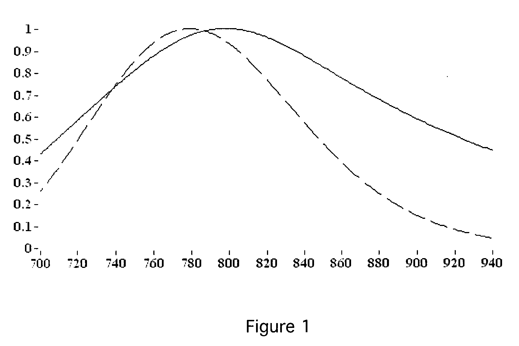
[0018] In the case of a custom-designed filter, the shift in and narrowing of the gain cross section of ti:sapphire with temperature is a rather small effect, but it turns out to be quite critical. The conventional gain-flattening filter design implemented for room temperature operation of ti:sapphire amplifiers does not work well at cryogenic temperatures, while the filter designed for cryogenic operation according to the present invention does not work at room temperatures. Overall the gain-flattening filter works much better and with much more repeatability in the cryo-cooled situation.
[0020] A preferred embodiment of the present invention uses a “multipass amplifier” configuration, wherein the pulses do not retrace exactly the same path through the laser crystal for many passes, but rather shift slightly for each pass until the final pass intersects a mirror, which removes the pulse from the amplifier for use as an output pulse. As a feature, the ultimate system output can be further optimized in a multipass configuration by inserting the spectral filter into the beam path for a variable number of passes. Causing the filter to intersect the beam for the first several passes but bypass it for the final several passes increases system gain and improves pulse shape.

Problems solved by technology

Gain narrowing has long been recognized as a problem in amplifiers where the beam passes through the amplifying medium multiple times (e.g. multipass configurations and regenerative configurations).
Since the pulse duration and spectral bandwidth have an inverse relationship, spectral narrowing corresponds to longer-duration pulses, which is generally undesirable.
The resulting gain shape achieved is not ideal however, as it is not flat but rather a double peak shape or else exhibits “hard edges” on the spectrum.
[1, 2] However, in this work one difficulty is that when the ti:sapphire or the like is cryogenically cooled, changes in the gain spectrum of the material result in a further narrowing of the output spectral bandwidth from the amplifier, beyond the inevitable narrowing in multipass and regenerative configurations discussed above.
Since the pulse duration and spectral bandwidth have an inverse relationship, spectral narrowing corresponds to longer-duration pulses, which is generally undesirable.
Hence a problem with cryogenically cooled ultrafast laser amplifier systems, especially multipass amplifiers, is a shift in the gain spectrum of ti:sapphire at cryogenic temperatures, along with a narrowing of the gain profile above and beyond the narrowing that occurs in room temperature systems.
The conventional gain-flattening filter designs implemented for room temperature operation of ti:sapphire amplifiers do not work well at cryogenic temperatures.
While the present inventors are experts in the field of cryogenically-cooled amplifiers, they were surprised by the poor performance of conventional filters in cryogenically-cooled amplifiers.
Even though the shift in gain cross section of ti:sapphire with temperature is a rather small effect, and it was not expected that changes to the filter would be required to effectively use the filter at cryo temperatures, it turns out to be quite critical.
Optimizing filters (and other elements of the amplifier) for use in cryogenically-cooled amplifiers was not intuitive and required a difficult iterative process, and even adjusting the temperature of the laser medium in order to match the profile obtained for the optimized filter.

Method used


Image

  • Gain flattening filter for preserving the spectral bandwidth in cryogenic ultrashort-pulse laser amplifiers
  • Gain flattening filter for preserving the spectral bandwidth in cryogenic ultrashort-pulse laser amplifiers
  • Gain flattening filter for preserving the spectral bandwidth in cryogenic ultrashort-pulse laser amplifiers

Examples


Embodiment Construction

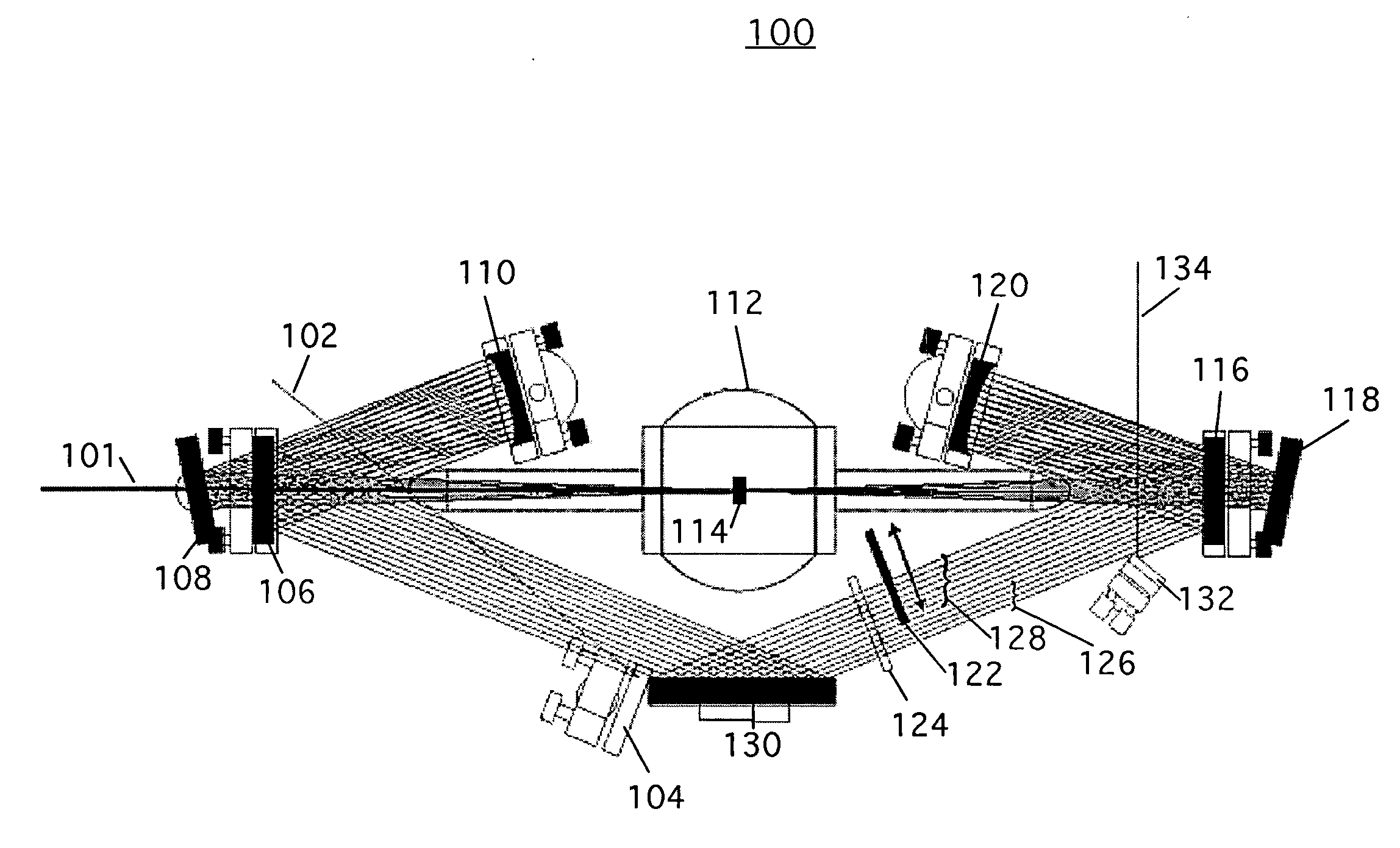
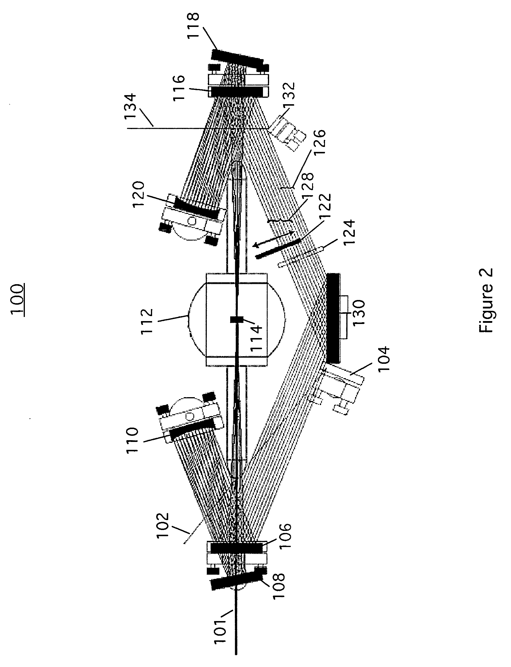
[0030]FIG. 2 is a block diagram of a preferred embodiment of a cryogenically cooled ultrafast ti:sapphire laser amplifier 100 using a gain flattening filter 122. The embodiment of FIG. 2 is a “multipass” amplifier configuration, wherein the beam shifts slightly in path with each pass, which allows the inclusion of an optional feature wherein filter 122 intersects the beam path for a variable number of passes—i.e. it intersects the first several passes 128, but the last several passes 126 bypass the filter. The final pass intersects output mirror 132 and is diverted out of the amplifier as output pulse 134.

[0031] Ultrafast laser amplifier system 100 takes an ultrashort light pulse 102, “stretches” it in time, then puts the beam through an amplification process that typically requires 8-20 passes through a laser crystal 114 to increase the output pulse 134 energy from ˜10−9 Joules to ˜10−3 J or higher. Pump beam 101 enters the system at the right in FIG. 2.

[0032] Input beam 102 refl...


PUM


Abstract

A gain flattening filter preserves very broad bandwidth, and therefore very short-duration pulses in ultrafast cryogenically-cooled laser amplifier systems, while also maintaining good overall efficiency. The filter is optimized for pulses amplified in a cryogenically cooled material.

Description

[0001] This application claims the benefit of U.S. Provisional Patent Application No. 60 / 706,389, filed Aug. 8, 2005.BACKGROUND OF THE INVENTION [0002] 1. Field of the Invention [0003] This invention relates to gain flattening filters for use in laser amplifiers. In particular, this invention relates to gain flattening filters optimized for use in cryogenic ultrashort-pulse laser amplifiers. [0004] 2. Description of Related Art [0005] Gain narrowing has long been recognized as a problem in amplifiers where the beam passes through the amplifying medium multiple times (e.g. multipass configurations and regenerative configurations). Both multipass and regenerative amplifiers pass the beam being amplified through the gain material a number of times, in order to achieve sufficient amplification. Since gain follows a generally bell-shaped curve, the repeated passes result not just in increased power, but also in narrowed gain profile. Since the pulse duration and spectral bandwidth have a...

Claims


Application Information

Patent Timeline
Patent Type & Authority Applications(United States)
IPC IPC(8): H01S3/00H04B10/12
CPCH01S3/005H01S3/0057H01S3/0078H01S3/025H01S3/0407H04B10/25073H01S3/1625H01S3/1636H01S3/2325H01S2301/02H01S2301/04H01S3/10023
Inventor BACKUS, STERLING J.KAPTEYN, HENRY C.
Owner UNIV OF COLORADO THE REGENTS OF
Learn More